Woodworking machine

A technology of woodworking machines and racks, which is applied to wood processing equipment, manufacturing tools, forming/shaping machines, etc., can solve the problems of poor positioning stability and achieve high positioning stability

Active Publication Date: 2020-06-30
吴善旺
View PDF9 Cites 3 Cited by
  • Summary
  • Abstract
  • Description
  • Claims
  • Application Information

AI Technical Summary

Problems solved by technology

[0005] The purpose of the present invention is to solve the above-mentioned problems in the existing technology, and propose a woodworking machine to solve the problem of poor positioning stability of the existing woodworking machine for workpieces with irregular shapes

Method used


Image

  • Woodworking machine
  • Woodworking machine
  • Woodworking machine

Examples


Embodiment 1

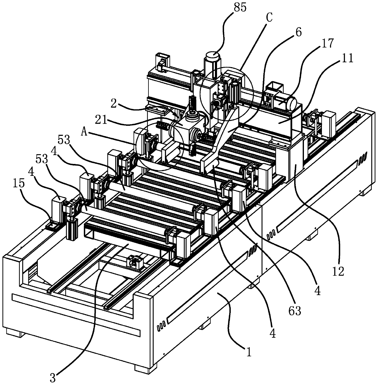
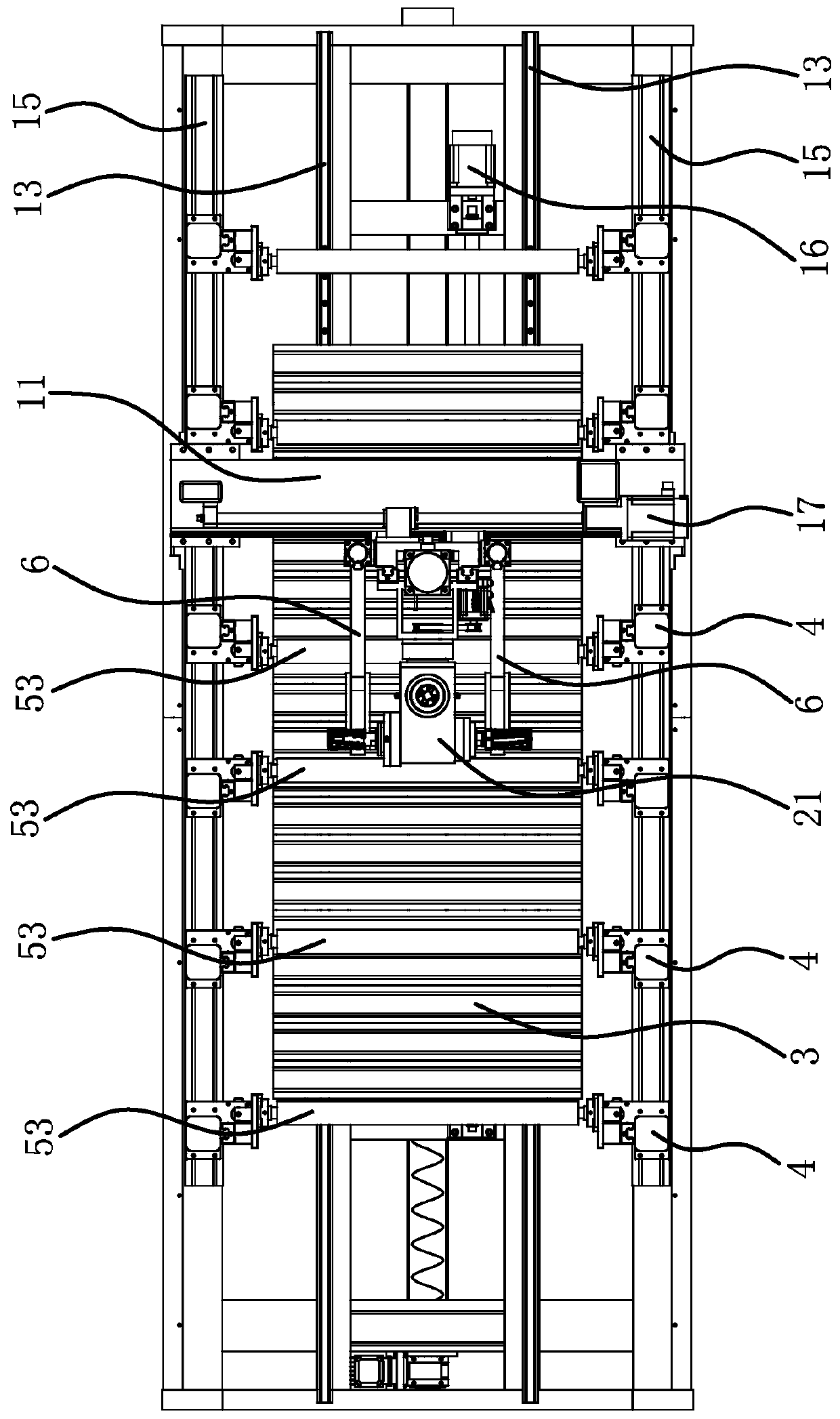
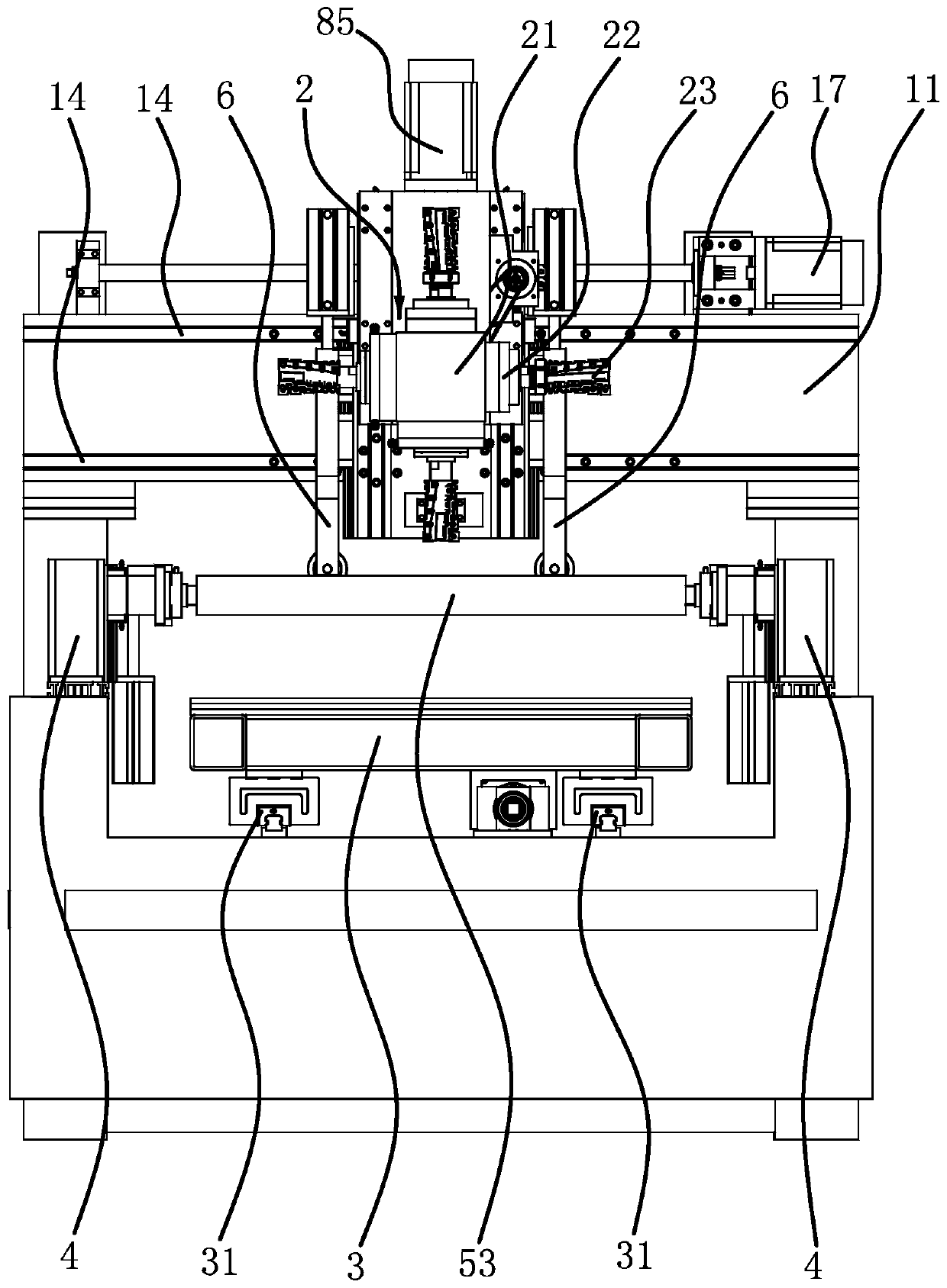
[0038] Such as Figure 1 to Figure 4 As shown, the woodworking machine includes a frame 1 and a cross beam 11. Vertical columns 12 are vertically fixed at the two sides of the frame 1 approximately in the middle of the longitudinal direction. The cross beam 11 is arranged in the transverse direction, and the two ends of the cross beam 11 are respectively fixed on the two columns. At the top of 12, a horizontal carriage 8 is slidably connected to one side of the cross beam 11 in a horizontal direction, a vertical carriage 9 is slidably connected to the side of the horizontal carriage 8 in a vertical direction, and a processing component is connected to the vertical carriage 9 2. The movement of the horizontal carriage 8 and the vertical carriage 9 realizes the horizontal and vertical movement of the processing assembly 2, and a processing platform 3 is slidably connected to the frame 1 along the longitudinal direction. The processing platform 3 is arranged horizontally, and its u...

Embodiment 2

[0043] The structure of the woodworking machine is basically the same as that of the first embodiment, the difference lies in Picture 9 , Picture 10 As shown, a guide sleeve 64 is provided in the connecting hole 621 of the positioning frame 6. The guide sleeve 64 includes a cylindrical holder 641. The holder 641 is uniformly distributed with through holes, and the through holes are provided with balls 642 and a longitudinal pressing roller 63 The connecting posts 631 at both ends are respectively penetrated in the two cages 641 and abut on the balls 642. The axial length of the longitudinal pressing roller 63 is smaller than the distance between the two connecting protrusions 62, and the connecting posts 631 are also sleeved A return spring 65, one end of the return spring 65 abuts against the end surface of the longitudinal pressing roller 63, and the other end abuts against the connecting protrusion 62, when the longitudinal pressing roller 63 is pressed against the workpiece...

Embodiment 3

[0045] The structure of the woodworking machine is basically the same as that of the first embodiment, the difference lies in Picture 11 , Picture 12 As shown, the longitudinal pressing roller 63 has a tubular shape. A connecting column 631 is fixed between the two connecting protrusions 62. The connecting column 631 is arranged in the longitudinal direction. The longitudinal pressing roller 63 is sleeved on the connecting column 631. The inner diameter of the longitudinal pressing roller 63 is larger than The outer diameter of the connecting column 631 is provided with a guide sleeve 64 at both ends of the longitudinal pressing roller 63. The guide sleeve 64 includes a cylindrical holder 641 which is sleeved on the connecting column 631. The holders 641 are both The through holes are arranged with balls 642. The inner side surface of the longitudinal pressing roller 63 and the outer side surface of the connecting post 631 abut on the balls 642, so that the longitudinal pressin...


PUM


Abstract

The invention provides a woodworking machine, belongs to the technical field of machining equipment and solves the problem that an existing woodworking machine is relatively poor in stability of positioning irregular shape workpieces. The woodworking machine comprises a rack and a cross beam fixed to the rack. A processing assembly is arranged on the cross beam, a processing platform is slidably arranged on the rack in the horizontal direction, three-dimensional translation is formed between the processing assembly and the processing platform, a plurality of transverse compression rollers capable of lifting are further horizontally arranged on the rack, the transverse compression rollers are arranged in the moving platform of the processing platform, longitudinal compression rollers whichare horizontally arranged and are capable of lifting are connected to the cross beam, the longitudinal compression rollers and the transverse compression rollers are arranged vertically, and the longitudinal compression rollers can descend to a placed between adjacent two transverse compression rollers. The woodworking machine is higher in stability of positioning the irregular shape workpieces.

Description

Technical field [0001] The invention belongs to the technical field of mechanical processing equipment and relates to a woodworking machine. Background technique [0002] Woodworking machines, such as engraving and milling machines, are processing equipment capable of engraving and milling workpieces. The engraving and milling machine is equipped with a motor that can move in multiple dimensions, and the output shaft of the motor is equipped with a tool to perform three-dimensional processing of the workpiece. The workpiece needs to be positioned on the processing platform, so there will be a positioning structure for positioning the workpiece on the processing platform, such as the sawing machine disclosed in the patent document (application number: 201320302954.9), including a wheel saw set on the frame Group, board moving guide device, motor, pressing plate device, dust removal device; pressing plate device is provided with cylinder racks on both sides of the moving rack surfa...

Claims


Application Information

Patent Timeline
Patent Type & Authority Applications(China)
IPC IPC(8): B27C5/02B27C5/06
CPCB27C5/02B27C5/06
Inventor 吴善旺
Owner 吴善旺
Why Eureka
Try Eureka