Zinc recovery method of blast furnace or shaft furnace and device adopted by zinc recovery method

A recovery device and recovery method technology, applied in the field of metallurgy, can solve the problems of solid waste pollution, waste of zinc resources, shortage of zinc resources, etc., and achieve the effects of less heat loss, reducing operating resistance, and solving the problem of direct production.

Pending Publication Date: 2020-06-30
SHENYANG DONGDASHANHUI ENVIRONMENTAL TECH CO LTD
View PDF0 Cites 11 Cited by
  • Summary
  • Abstract
  • Description
  • Claims
  • Application Information

AI Technical Summary

Problems solved by technology

[0007] There is a shortage of zinc resources in my country. On the one hand, a large amount of zinc ore is imported ev...

Method used


Image

  • Zinc recovery method of blast furnace or shaft furnace and device adopted by zinc recovery method
  • Zinc recovery method of blast furnace or shaft furnace and device adopted by zinc recovery method
  • Zinc recovery method of blast furnace or shaft furnace and device adopted by zinc recovery method

Examples


Embodiment 1

[0041] A steel company, 30m 3 The blast furnace smelting furnace is used for the recovery and treatment of zinc-containing iron and steel dust. Due to the excessive zinc load, the furnace is often shut down for cleaning due to too much blast resistance. Each cleaning will remove several tons of zinc, and there are also solidified zinc in the gaps in the furnace wall. , Has a great influence on the life of the furnace body.

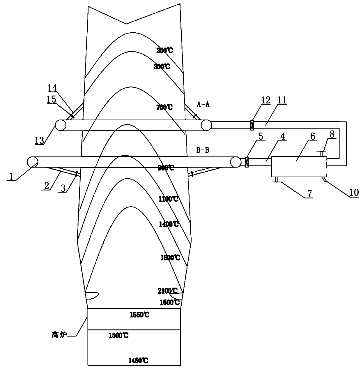
[0042] A method for recovering zinc from a blast furnace or a shaft furnace includes the following steps:

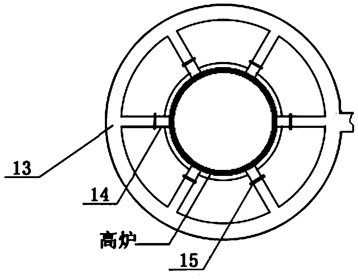
[0043] Step 1. Set up the annular flue:

[0044] During the overhaul of the blast furnace smelting furnace, according to the distribution area of ​​zinc in the smelting furnace, 3 In the blast furnace at 750°C, there are 6 air outlets, and the flue gas ring flue 1 is set outside the blast furnace. The flue gas ring flue 1 is provided with 6 air holes of the same number and size as the blast furnace air holes. The air outlet of the blast furnace is connecte...

Embodiment 2

[0056] An iron and steel enterprise has an all-scrap steel-making shaft furnace. After the shaft furnace is equipped with a high-temperature gas producer, the gas temperature after the gas producer is higher than 1000℃, and the high-temperature gas returns to the shaft furnace to preheat the scrap, and the flue gas in the furnace is a reducing atmosphere , The scrap steel used in the shaft furnace is all crushed material, and the zinc content is relatively high. The steel-making shaft furnace can produce 90 tons of steel per hour. It is difficult to induce air during the operation. After the furnace is shut down, it is found that the charge is blocked due to zinc enrichment.

[0057] A method for recovering zinc from a shaft furnace includes the following steps:

[0058] Step 1. Set up the annular flue:

[0059] According to the distribution area of ​​zinc in the shaft furnace smelting furnace, 8 air outlets are opened in the 720 ℃ area of ​​the shaft furnace, and the flue gas ring f...


PUM


Abstract

The invention discloses a zinc recovery method of a blast furnace or shaft furnace and a device adopted by the zinc recovery method, and belongs to the technical field of metallurgy. The zinc recoverydevice comprises an extracted smoke annular flue, an extracted smoke pipe, an extracted smoke pipeline, a heat exchanger, a returned smoke pipeline, a returned smoke annular pipeline and a returned smoke pipe. According to the zinc recovery method of the blast furnace or shaft furnace and the device adopted by the zinc recovery method, the annular flues are arranged in an area with high zinc vapor pressure of the blast furnace or the shaft furnace, the pipelines are used for guiding smoke out of the furnace and enters the heat exchanger to be condensed for zinc recovery, and metal state recycling of zinc in the blast furnace or shaft furnace is achieved. According to the method and device, the smelting prograding problem of high-zinc materials is achieved, and therefore the high-zinc materials can be normally used, solid waste is turned into valuable resources, and metal state recovery of valuable metal zinc of the high-zinc materials is achieved; and a large amount of zinc can be obtained, and the zinc resource shortage problem of our country is relieved.

Description

Technical field [0001] The invention belongs to the technical field of metallurgy, and particularly relates to a zinc recovery method and device for a blast furnace or a shaft furnace. Background technique [0002] In the process of blast furnace ironmaking, shaft furnace steelmaking or direct reduction shaft furnace smelting, zinc will be repeatedly cyclically enriched in the furnace, resulting in poor furnace conditions and affecting production efficiency. [0003] During blast furnace smelting, there is zinc oxide or metallic zinc in the materials. Among them, zinc oxide is reduced to metallic zinc by reducing gas, and metallic zinc is vaporized at high temperature into zinc vapor. The zinc vapor rises in the furnace with the flue gas and encounters low temperature materials. It is condensed into liquid zinc or solid zinc. As the temperature of the material rises, it is vaporized into zinc vapor. This is repeated in the furnace. When the enrichment reaches a certain level, the g...

Claims


Application Information

Patent Timeline
IPC IPC(8): C22B19/18C21B5/00C21B11/02C22B7/02
CPCC21B5/00C21B11/02C22B7/001C22B7/02C22B19/18Y02P10/20
Inventor 孙中强
Owner SHENYANG DONGDASHANHUI ENVIRONMENTAL TECH CO LTD
Why Eureka
Try Eureka