
Damping roller type electric two-way tamping machine

A vibration-damping roller and tamping machine technology, which is applied to the upper structure of the track, roads, tracks, etc., can solve the problems of easy swing, the tamping machine cannot meet the operation requirements, and affect the working efficiency of the tamping machine, so as to improve the use of the tamping machine. sexual effect

Inactive Publication Date: 2020-06-30
袁建国
View PDF7 Cites 0 Cited by
  • Summary
  • Abstract
  • Description
  • Claims
  • Application Information

AI Technical Summary

Problems solved by technology

[0005] Aiming at the deficiencies in the prior art, the purpose of the present invention is to provide a vibration-damping roller type electric two-way tamping machine to solve the problem that the tamping guide rod lacks effective positioning and restraint capabilities when the existing tamping machine is tamping. , leading to the phenomenon that the tamping guide rod is prone to swing under the impact operation of the hammer head, which affects the effective force of the hammer head when it impacts the material, reduces the positioning stability between the guide rod and the driving wheel, and increases the friction force. Frequent shutdowns are required to adjust the positioning gap between the guide rail and the friction wheel, which seriously affects the working efficiency of the tamping machine; There are changes in the type of turnout, and the geometric dimensions of the turnout are also constantly changing, which leads to the problem that the tamping machine cannot meet the operation requirements and reduces the usability of the tamping machine

Method used


Image

  • Damping roller type electric two-way tamping machine
  • Damping roller type electric two-way tamping machine
  • Damping roller type electric two-way tamping machine

Examples


Embodiment Construction

[0031] In order to make the technical means, creative features, goals and effects achieved by the present invention easy to understand, the present invention will be further described below in conjunction with specific embodiments.

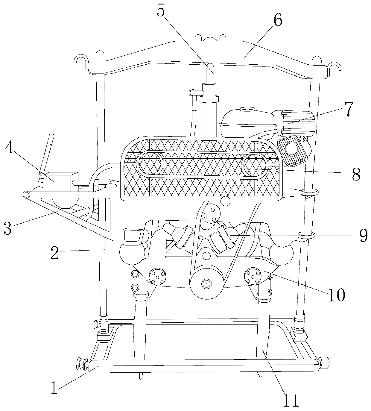
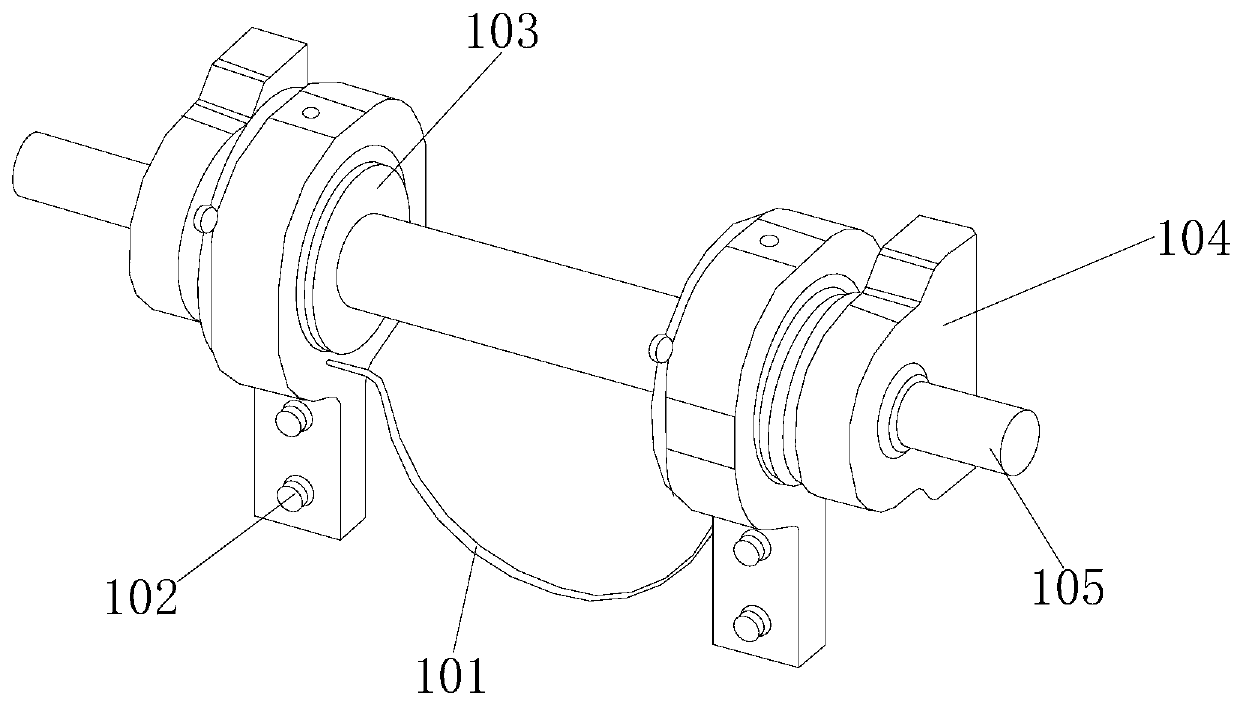
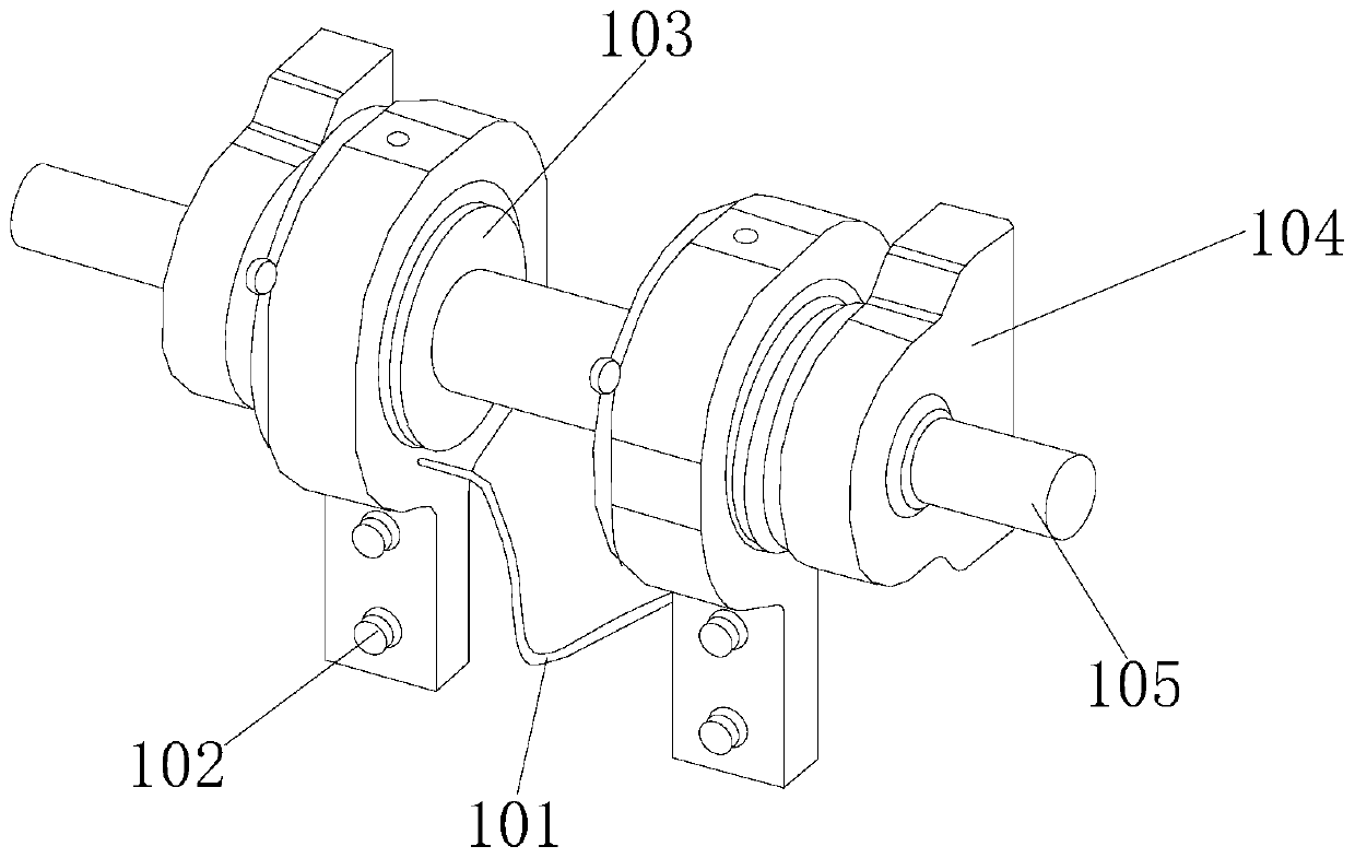
[0032] see Figure 1-Figure 8, the present invention provides a reduction technical solution: a vibration reduction roller type electric two-way tamping machine, its structure includes a fixed frame 1, a sliding rod 2, a sound insulation board 3, a control rod 4, a piston hammer rod 5, a fixed plate 6, Motor 7, muffler 8, driving mechanism 9, adjusting device 10, tamping device 11, described sliding rod 2 is connected on fixed frame 1 by lower end slide block and carries out forward and backward movement, described sliding rod 2 tops and fixed plate 6 Connected in a penetrating manner, the sliding rod 2 is arranged on the left and right sides of the sound insulation board 3, the left side of the sound insulation board 3 is provided with a control ...


PUM


Abstract

The invention discloses a damping roller type electric two-way tamping machine. The damping roller type electric two-way tamping machine structurally comprises a fixing frame, a sliding rod, a sound insulation plate, a control rod, a piston hammer rod, a fixing plate, a motor, a silencer, a driving mechanism, an adjusting device and a tamper. After the improvement, when the damping roller type electric two-way tamping machine operates, the drive motor operates, the adjusting rotary buckle rotates on the main body; the adjusting hammer block adjusts the width on the movable rod according to thegeometric dimension of the turnout; the adjusting hammer block is fixed at an adjusting position by a limiting strip; the adjusting hammer block can be changed according to the geometric dimension ofthe turnout; the tamper can meet the operation requirements; the telescopic piece is adjusted to the using position through the positioning piece, the positioning clamping block and the guide wheel are matched with the tamping guide rod to drive the bearing rod and the hammer head to tamp the sleeper, the phenomenon that the hammer head swings under the impact operation is prevented, the positioning stability between the tamping guide rod and the tamper is guaranteed, the friction force is reduced, and the working efficiency of the tamper is improved.

Description

technical field [0001] The invention relates to the field of railway construction, in particular to a vibration-damping roller type electric two-way tamping machine. Background technique [0002] The purpose of the tamping machine is to increase the firmness and stability of the track bed and the rails. When the train passes through the turnout, the force is very uneven, which has a great impact on the rails and the track bed, and it is easier to loosen the track bed and the rails, which affects driving safety. , so the turnout also needs to be tamped. When the tamping machine is tamping, the areas that need to be improved: [0003] 1. When the existing tamping machine is tamping, the tamping guide rod lacks effective positioning and restraint capabilities, which leads to the phenomenon that the tamping guide rod is prone to swing under the impact operation of the hammer head, which affects the impact of the hammer head. The effective force when the material impacts reduces...

Claims


Application Information

Patent Timeline
IPC IPC(8): E01B27/20
CPCE01B27/20E01B2203/12E01B2203/125
Inventor 袁建国
Owner 袁建国
Learn More