
Quantitative Measurement System of Hydraulic Damping Ratio of Rotating Centrifugal Impeller

A rotary centrifugal, quantitative measurement technology, used in non-variable-capacity pumps, pump control, machines/engines, etc., can solve the problem of inability to quantitatively measure the hydraulic damping ratio of centrifugal impellers

Active Publication Date: 2021-02-19
CHINA AGRI UNIV
View PDF4 Cites 0 Cited by
  • Summary
  • Abstract
  • Description
  • Claims
  • Application Information

AI Technical Summary

Problems solved by technology

[0006] The purpose of the present invention is to provide a quantitative measurement system for the hydraulic damping ratio of a rotating centrifugal impeller to solve the technical problem in the prior art that the hydraulic damping ratio of the centrifugal impeller cannot be quantitatively measured under rotating motion

Method used


Image

  • Quantitative Measurement System of Hydraulic Damping Ratio of Rotating Centrifugal Impeller
  • Quantitative Measurement System of Hydraulic Damping Ratio of Rotating Centrifugal Impeller
  • Quantitative Measurement System of Hydraulic Damping Ratio of Rotating Centrifugal Impeller

Examples


Embodiment Construction

[0040]The specific implementation manners of the present invention will be further described in detail below in conjunction with the accompanying drawings and embodiments. The following examples are used to illustrate the present invention, but are not intended to limit the scope of the present invention.

[0041] In describing the present invention, it should be understood that the terms "center", "longitudinal", "transverse", "length", "width", "thickness", "upper", "lower", "front", " Back", "Left", "Right", "Vertical", "Horizontal", "Top", "Bottom", "Inner", "Outer", "Clockwise", "Counterclockwise", "Axial", The orientation or positional relationship indicated by "radial", "circumferential", etc. is based on the orientation or positional relationship shown in the drawings, and is only for the convenience of describing the present invention and simplifying the description, rather than indicating or implying the referred device or element Must be in a particular orientation...


PUM


Abstract

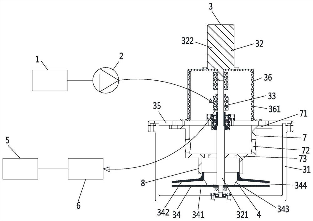
The invention relates to the technical field of operational stability of hydraulic machines, and discloses a quantitative measurement system for the hydraulic damping ratio of a rotating centrifugal impeller. The quantitative measurement system comprises a signal generator, an excitation signal amplifier, a quantitative measurement device for the hydraulic damping ratio of the rotating centrifugalimpeller, vibration excitation pieces, a response signal processor and an acquisition card, wherein the excitation signal amplifier is electrically connected with the signal generator; the quantitative measurement device for the hydraulic damping ratio of the rotating centrifugal impeller comprises a water storage container, a variable speed motor, a slip ring and the rotating centrifugal impeller; the multiple vibration excitation pieces are used for exciting the rotating centrifugal impeller to vibrate in the axial direction and used for obtaining responses of the rotating centrifugal impeller and can actively control vibration excitation and response acquisition modes; the acquisition card is electrically connected with the response signal processor; and the acquisition card is electrically connected with the slip ring, and the response signal processor can calculate the hydraulic damping ratio by fitting slip ring output signals sent by the acquisition card. The quantitative measurement system for the hydraulic damping ratio of the rotating centrifugal impeller has the advantage of quantitatively measuring the hydraulic damping ratio of the centrifugal impeller under rotatingmotion.

Description

technical field [0001] The invention relates to the technical field of hydraulic machinery operation stability, in particular to a quantitative measurement system for the hydraulic damping ratio of a rotary centrifugal impeller. Background technique [0002] Centrifugal pumps are widely used in the fields of agriculture, industry and domestic water supply, and have high requirements on the service life and operation stability of the impeller. When the centrifugal pump is running at high speed, severe abnormal vibration may occur under certain conditions. To avoid such vibrations, vibrations need to be accurately predicted during the design phase. Additional damping is the key input parameter for the vibration prediction of the pump type, among which the hydraulic damping ratio is the most critical. [0003] The internal flow state of a rotating centrifugal impeller is much more complicated than that of a non-rotating uniform flow. Under the influence of dynamic and static...

Claims


Application Information

Patent Timeline
Patent Type & Authority Patents(China)
IPC IPC(8): F04D15/00
CPCF04D15/0088
Inventor 姚志峰曾永顺齐鑫刘婧张世杰王福军肖若富
Owner CHINA AGRI UNIV
Learn More