An environmentally friendly waste heat recovery device for waste gas treatment

A waste heat recovery device and waste gas treatment technology, applied in the field of machinery, can solve the problems of limited waste heat absorption capacity of waste gas, waste of water resources, affecting the efficiency of waste heat absorption of waste gas, etc., so as to improve the efficiency of flow, promote uniform distribution, and promote uniformity The effect of distribution

Active Publication Date: 2021-11-02
HEBEI HUATONG INNOVATION TECH
View PDF7 Cites 0 Cited by
  • Summary
  • Abstract
  • Description
  • Claims
  • Application Information

AI Technical Summary

Problems solved by technology

It only increases the contact area between water and exhaust gas through the bent coiled tube, so as to achieve high efficiency of waste heat recovery and utilization, but it still has the following shortcomings: First, due to the continuous flow of water in the coiled tube, its contact time with hot air is limited , there are requirements for the speed of water flow and the flow speed of hot exhaust gas. When the speeds of the two do not match, it will cause waste of heat energy of exhaust gas or waste of water resources, and it is impossible to realize effective recovery of waste heat of exhaust gas; secondly, it only The area in contact with the exhaust gas is increased through the curved coiled tube. This method is still relatively passive to absorb the waste heat of the exhaust gas, and the ability to absorb the waste heat of the exhaust gas is limited; finally, when heating, only the water in contact with the inner wall of the coiled tube can be heated, and the inner center of the coiled tube The water in the area is heated slowly, and the heat cannot be evenly distributed in the water, which affects the efficiency of absorbing waste heat from exhaust gas

Method used


Image

  • An environmentally friendly waste heat recovery device for waste gas treatment
  • An environmentally friendly waste heat recovery device for waste gas treatment
  • An environmentally friendly waste heat recovery device for waste gas treatment

Examples


Embodiment Construction

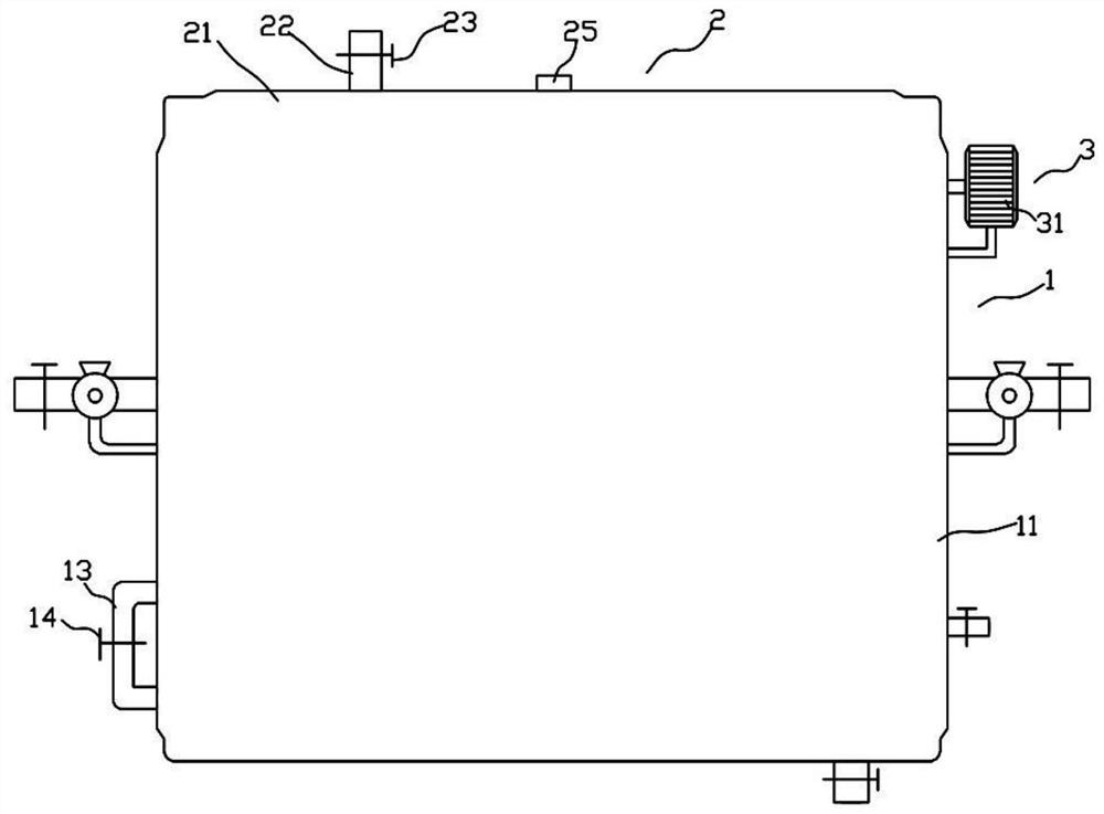
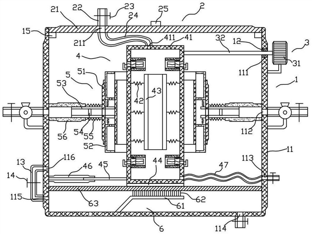
[0017] Such as Figure 1 to Figure 6 As shown, the environmental protection waste heat recovery device for waste gas treatment of the present invention includes a shell structure 1, a closed structure 2 arranged on the shell structure 1, a driving structure 3, a liquid collection structure 4 accommodated in the shell structure 1, and a The gas-collecting structure 5 around the liquid-collecting structure 4 and the heat-conducting structure 6 below the liquid-collecting structure 4 .

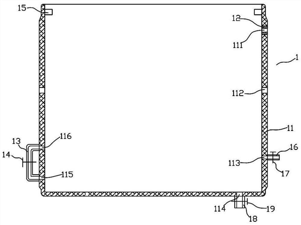
[0018] Such as Figure 1 to Figure 3 As shown, the housing structure 1 includes a housing 11, a sealing block 12 disposed on the housing 11, a connecting pipe 13 disposed outside the housing 11, a first valve 14 disposed on the connecting pipe 13, and a valve housed in the housing. The support blocks 15 on the left and right sides in 11, the liquid outlet pipe 16 located outside the housing 11, the second valve 17 arranged on the liquid outlet pipe 16, the air outlet pipe 18 located below the ho...


PUM


Abstract

An environment-friendly waste heat recovery device for waste gas treatment, comprising a shell structure (1) and a closed structure (2) arranged on the shell structure (1), the environment-friendly waste heat recovery device for waste gas treatment also includes a housing The liquid collection structure (4) in the housing structure (1), the gas collection structure (5) arranged around the liquid collection structure (4), the liquid collection structure (4) includes a heat conducting frame (41 ), a number of first springs (42) housed in the heat conduction frame (41), a stirring frame (43), a heat conduction plate (44) located below the heat conduction frame (41), a heat conduction plate (44) located under the heat conduction frame (41 ) a positioning rod (45) on one side, a positioning frame (46), a second hose (47) located on the other side of the heat conducting frame (41), several sealing frames accommodated in the heat conducting frame (41) (48). The invention can effectively evenly distribute the heat in the heat conduction frame in the water, and is beneficial to ensure the heat absorption efficiency of the water in the heat conduction frame in contact with the inner wall.

Description

technical field [0001] The invention relates to the field of mechanical technology, in particular to an environment-friendly waste heat recovery device for waste gas treatment. Background technique [0002] In the chemical industry and other fields, a large amount of high-temperature exhaust gas will be generated. These exhaust gases are high in temperature and are generally discharged directly, which will not only cause environmental pollution, but also cause waste of energy, which is not economical and environmentally friendly. [0003] Chinese patent CN104121789A discloses an energy-saving waste gas waste heat recovery system, including: a waste gas channel and a water flow channel. Inside, the water flow channel is a continuously bent serpentine pipe, the two ends of the water flow channel are water inlet and water outlet respectively, and the water inlet and water outlet run through the pipe wall of the waste gas channel. It only increases the contact area between wate...

Claims


Application Information

Patent Timeline
Patent Type & Authority Patents(China)
IPC IPC(8): F28D21/00B01D46/30B01D46/42B01D46/00
CPCB01D46/00B01D46/30B01D46/4263F28D21/0003
Inventor 袁淑军
Owner HEBEI HUATONG INNOVATION TECH
Why Eureka
Try Eureka