A method and system for detecting particle mass flow rate during pneumatic conveying

A particle mass and pneumatic conveying technology, applied in mass flow measurement devices, indirect mass flow meters, measurement flow/mass flow, etc., can solve problems such as large measurement errors, improve performance, improve reliability and detectability , the effect of improving the spatial resolution

Active Publication Date: 2021-02-09
ZHEJIANG UNIV
View PDF9 Cites 0 Cited by
  • Summary
  • Abstract
  • Description
  • Claims
  • Application Information

AI Technical Summary

Problems solved by technology

Based on the above method, the measurement of particle mass flow rate under a single delivery flow pattern can be realized, but when the delivery flow pattern changes, the measurement error will be large

Method used


Image

  • A method and system for detecting particle mass flow rate during pneumatic conveying
  • A method and system for detecting particle mass flow rate during pneumatic conveying
  • A method and system for detecting particle mass flow rate during pneumatic conveying

Examples


Embodiment 1

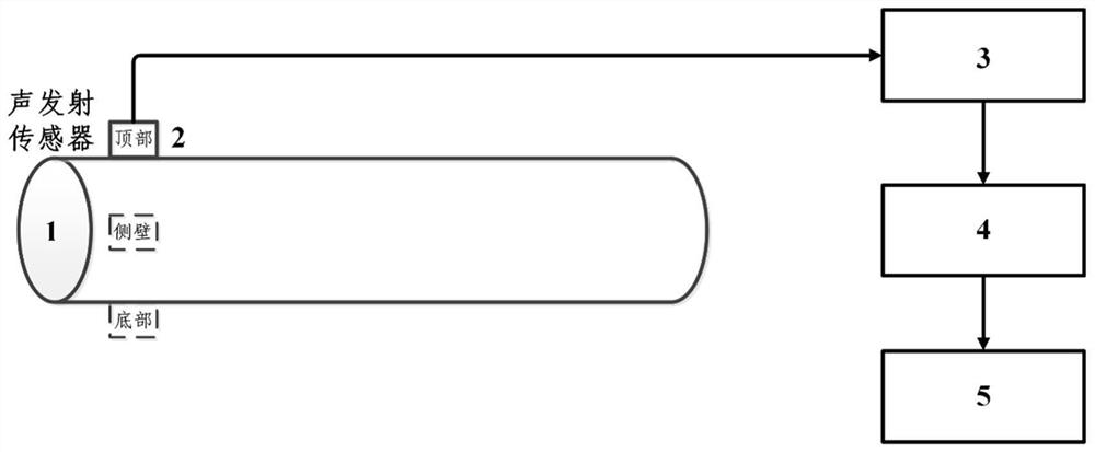
[0057] like figure 1 As shown, the detection device of this embodiment includes a horizontal material conveying pipeline 1, a group of acoustic wave sensor groups 2, a signal amplification device 3, a signal acquisition device 4, and a signal processing device 5; The sensor group 2 is connected to the signal amplifying device 3 to convert the acoustic signal into an electrical signal and transmit it to the signal amplifying device 3, and the signal amplifying device 3 is connected to the signal collecting device 4 to transmit the amplified signal to the signal collecting device 4, and the signal collecting device 4 and The signal processing device 5 is connected to analyze the collected signals.

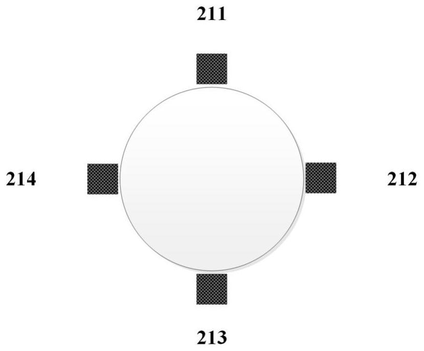
[0058] like figure 2 As shown, in this embodiment, the acoustic wave sensor group 2 includes four acoustic wave sensors, the four acoustic wave sensors are respectively 211, 212, 213 and 214, which are evenly distributed along the same circular section of the pipeline 1, and the in...

Embodiment 2

[0065] like figure 1 As shown, the detection device of this embodiment includes a horizontal material conveying pipeline 1, a group of acoustic wave sensor groups 2, a signal amplification device 3, a signal acquisition device 4, and a signal processing device 5; The sensor group 2 is connected with the signal amplifying device 3 to convert the acoustic signal into an electrical signal and transmit it to the signal amplifying device 3, and the signal amplifying device 3 is connected with the signal collecting device 4 to transmit the amplified signal to the signal collecting device 4, and the signal collecting device 4 and The signal processing device 5 is connected to analyze the collected signals.

[0066] like figure 2As shown, in this embodiment, the acoustic wave sensor group 2 includes four acoustic wave sensors, the four acoustic wave sensors are respectively 211, 212, 213 and 214, which are evenly distributed along the same circular section of the pipeline 1, and the...


PUM


Abstract

The invention discloses a method and a system for detecting the mass flow rate of particles in a pneumatic conveying process, and the mass flow rate of materials conveyed in a pipeline is accurately detected through a series of treatment by collecting sound wave signals generated by the action of fluid particles in the pipeline and the wall surface of the pipeline in a non-invasive manner. The sound wave detection adopted by the invention is a non-invasive detection method, and the detection device is simple, safe, environment-friendly and suitable for online detection in the industrial production process. By adopting an acoustic sensor array, through data fusion of multiple sensors, particle flow forms, concentrations and speed distribution under different conveying flow patterns can be effectively associated with the conveying mass flow rate, so that the mass flow rate of conveyed particles can be accurately detected under different conveying conditions (different conveying flow patterns, different conveying pipelines and different conveying materials). Compared with an existing mass flow rate detection technology, the method is more sensitive, accurate and wider in application range.

Description

technical field [0001] The invention relates to the detection field of conveying parameters in the process of pneumatic conveying, in particular to a method and system for detecting the mass flow rate of particles in the conveying process. Background technique [0002] Pneumatic conveying is a typical gas-solid two-phase flow operation process to transport solid particles through the action of gas, and is widely used in chemical, metallurgical, pharmaceutical and other production processes. In practical applications, in order to meet the continuous measurement required in the production process and adjust the optimal conveying conditions in time to reduce conveying energy consumption and particle wear, real-time online detection of particle mass flow rate during pneumatic conveying is very important. [0003] Since pneumatic conveying belongs to the flow of gas-solid two-phase flow, different from single-phase flow, there are interface effects and relative velocities between...

Claims


Application Information

Patent Timeline
Patent Type & Authority Patents(China)
IPC IPC(8): G01F1/76G01F1/86G01F1/66
CPCG01F1/66G01F1/76G01F1/86
Inventor 杨遥张鹏孙婧元黄正梁王靖岱蒋斌波廖祖维阳永荣
Owner ZHEJIANG UNIV
Why Eureka
Try Eureka