Model placing rack for product design

A technology for product design and shelf placement, applied in applications, display hangers, display shelves, etc., can solve problems such as easy to drop, poor safety, and inconvenient product model observation, and achieve high safety and strong practicability

Inactive Publication Date: 2020-07-03
河南工学院
View PDF6 Cites 3 Cited by
  • Summary
  • Abstract
  • Description
  • Claims
  • Application Information

AI Technical Summary

Problems solved by technology

The general product design model needs to be replaced when the product is updated. The general shelf is not easy to open and place, and it is not convenient to observe the product model in all directions. The existing product model shelf is relatively fixed and difficult to carry. Unstable and easy to drop
[0003] The Chinese patent authorization announcement number is CN 209315392 U, which discloses a model placement rack for product design, which is convenient for product models to be stably placed on the rotating display stand, and the rotating display stand rotates the product model, which is convenient for all-round display and stable rotation The mechanism is convenient for stable support. The tempered glass display box is assembled with fou

Method used


Image

  • Model placing rack for product design
  • Model placing rack for product design
  • Model placing rack for product design

Examples


Embodiment 1

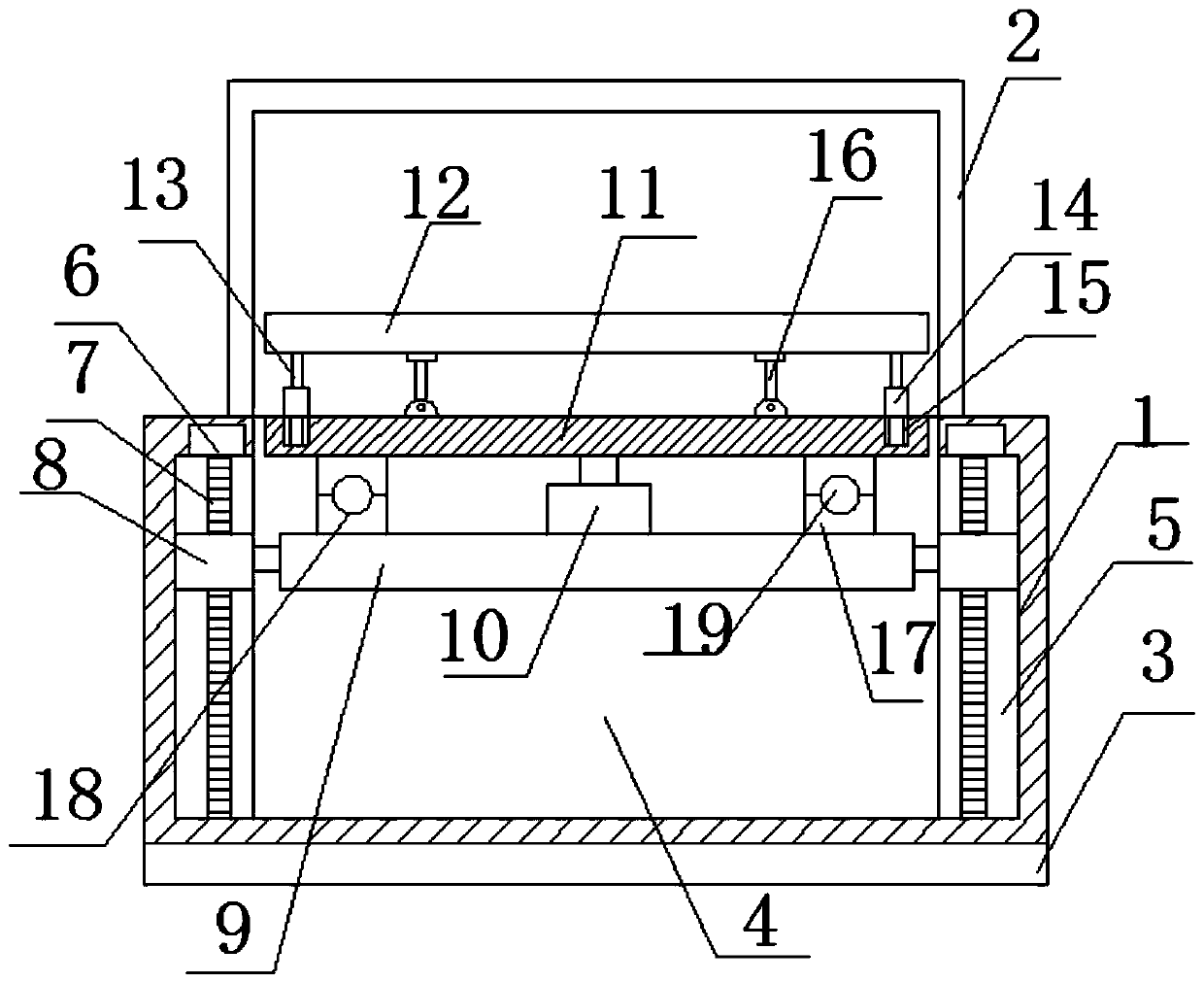
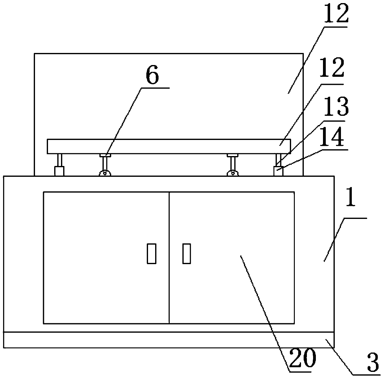
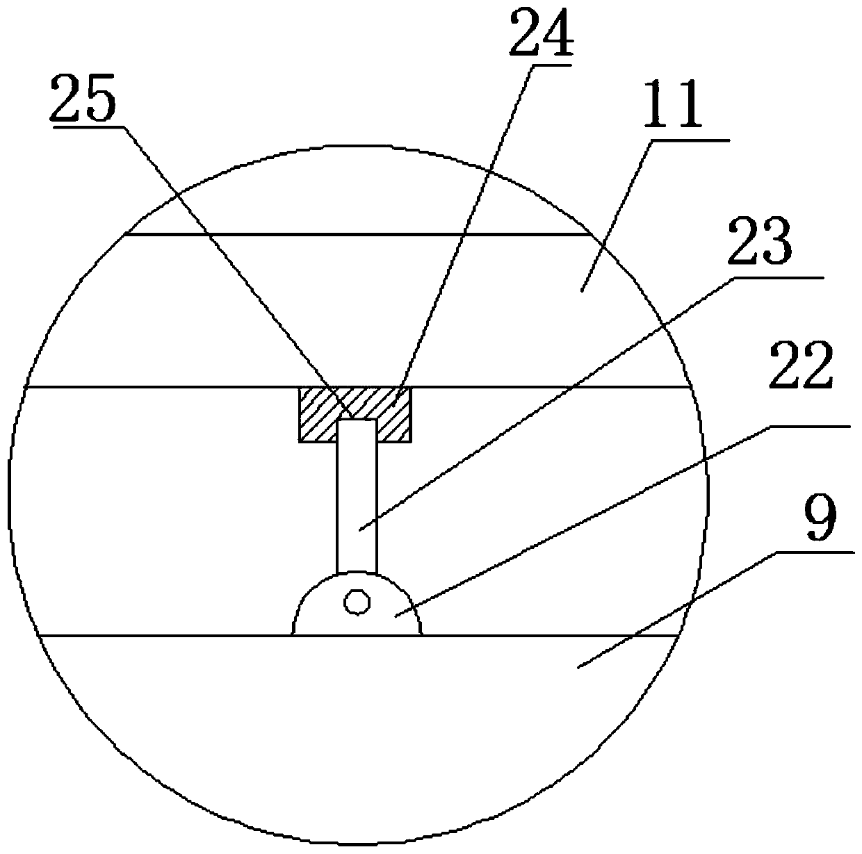
[0021] see Figure 1~3 , in the embodiment of the present invention, a kind of product design model placement rack, comprises workbench 1, and the upper end of described workbench 1 is provided with glass cover 2, and the lower end of workbench 1 is provided with anti-slip pad 3, and the inside of workbench 1 A cavity 4 is provided, the front side of the cavity 4 is provided with a box door 20, the left and right ends of the cavity 4 are provided with a lifting chamber 5, and the upper end of the lifting chamber 5 is provided with a lifting motor 6, and the lifting motor 6 The output end of 6 is provided with a threaded rod 7, and the threaded rod 7 is threaded with a lifting seat 8, and a lifting plate 9 is arranged between the two lifting seats 8, and a rotating motor 10 is arranged in the middle of the upper side of the lifting plate 9. The upper end of the rotating motor 10 is provided with a rotating plate 11, the top of the rotating plate 11 is provided with a placement ...

Embodiment 2

[0024] On the basis of Embodiment 1, the anti-slip mat 3 is an ABS anti-slip mat, and the lower side of the anti-slip mat 3 is provided with a number of adsorption grooves. It can play the role of anti-slip and improve the stability of the device when it is working.

Embodiment 3

[0026] refer to Figure 4 , On the basis of Embodiment 1 or Embodiment 2, a protective cover 26 is provided on the outside of the rotating electrical machine 10, and a sound insulation pad 27 is provided between the protective cover 26 and the rotating electrical machine 10, which can reduce the noise generated by the motor operation , to improve the comfort of use, a shock-absorbing pad 28 is arranged between the sound-insulating pad 27 and the rotating motor 10, which can reduce the vibration generated when the motor works, and the protective cover 26 is made of heat-dissipating material, and the protective cover 26 is connected with the rotating motor A number of heat conducting rods 29 are arranged between the motors 10 , and a number of cooling fins 30 are arranged outside the protective cover 26 . It is convenient to dissipate the heat of the motor and realize the protection of the motor.


PUM


Abstract

The invention relates to the technical field of product design and discloses a model placing rack for product design. The model placing rack comprises a workbench and a glass cover is arranged at theupper end of the workbench. An anti-skid pad is arranged at the lower end of the workbench; a cavity is formed in the workbench. A box door is arranged on the front side of the cavity; lifting cavities are formed in the left and right ends of the cavity; a lifting motor is arranged at the upper end of the lifting cavity; a threaded rod is arranged at the output end of the lifting motor; the threaded rod is in threaded connection with lifting seats; a lifting plate is arranged between the two lifting seats, a rotating motor is arranged in the middle of the upper side of the lifting plate, a rotating plate is arranged at the upper end of the rotating motor, a placing seat is arranged above the rotating plate, and due to the structural arrangement of the model placing rack, when a model is replaced, manual carrying is not needed, time and labor are saved, the safety is high, and the practicability is high.

Description

technical field [0001] The invention relates to the technical field of product design, in particular to a model placing frame for product design. Background technique [0002] Product design is a creative comprehensive information processing process. Through the combination of various elements such as lines, symbols, numbers, colors, etc., the shape of the product is displayed in a plane or three-dimensional form. The process of transforming into a specific physics or tool is the process of expressing a plan, planning assumption, and problem-solving method in an ideal form through specific operations. The general product design model needs to be replaced when the product is updated. The general shelf is not easy to open and place, and it is not convenient to observe the product model in all directions. The existing product model shelf is relatively fixed and difficult to carry. Unstable and easy to drop. [0003] The Chinese patent authorization announcement number is CN 2...

Claims


Application Information

Patent Timeline
IPC IPC(8): A47F5/025A47F5/10A47F3/00
CPCA47F3/004A47F3/005A47F5/025A47F5/10
Inventor 李云
Owner 河南工学院
Why Eureka
Try Eureka