
Compressor for preventing jugular phlebectopia of peripherally inserted central catheter (PICC)

A technology for internal jugular veins and compressors, which is applied in the field of compressors, can solve the problems of patient catheterization tension, patient cooperation difficulties, and waste of labor costs, so as to prevent internal jugular vein ectopia, avoid internal jugular vein ectopia, and avoid The effect of waste of labor cost

Pending Publication Date: 2020-07-03
BEIJING CHAOYANG HOSPITAL CAPITAL MEDICAL UNIV
View PDF0 Cites 1 Cited by
  • Summary
  • Abstract
  • Description
  • Claims
  • Application Information

AI Technical Summary

Problems solved by technology

[0003] At present, the clinical method used to reduce the ectopic internal jugular vein is mainly the internal jugular vein occlusion method. The traditional internal jugular vein occlusion method is that when the tip of the catheter is sent to the shoulder joint, the patient's head is biased to the puncture side, and the mandible is close to the shoulder. After continuing to deliver the tube, there are some difficulties in the cooperation of the patient, especially the emotional tension of the patient during the tube insertion, and it is often difficult to keep the chin close to the shoulder. Even if the chin is as close to the shoulder as possible, for thin patients, the entrance of the internal jugular vein is still hollow. state, there is still a certain probability of catheter ectopic
Another researcher tried to reduce the ectopic internal jugular vein by compressing the internal jugular vein with an ultrasound probe, but this required the cooperation of another PICC nurse or a nurse with ultrasound capabilities, resulting in a waste of labor costs

Method used


Image

  • Compressor for preventing jugular phlebectopia of peripherally inserted central catheter (PICC)
  • Compressor for preventing jugular phlebectopia of peripherally inserted central catheter (PICC)
  • Compressor for preventing jugular phlebectopia of peripherally inserted central catheter (PICC)

Examples


Embodiment 1

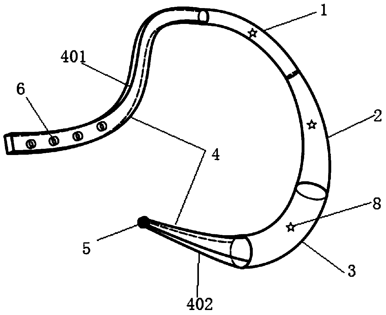
[0041] Such as figure 1 As shown, the present embodiment provides a compressor for preventing PICC cannulation of internal jugular vein ectopy, including:

[0042] No. I compression column 1, No. II compression column 2 and No. III compression column 3, the first end of the No. I compression column 1 forms a free end, and the second end of the No. I compression column 1 is connected to the No. II compression column. The first end of the column 2 is fixedly connected, the first end of the No. III compression column 3 is fixedly connected with the second end of the No. II compression column 2, and the second end of the No. III compression column 3 forms a free end, Thus the three are connected to each other and form an arc-shaped structure;

[0043] Elastic band 4, described elastic band 4 comprises No. 1 elastic band 401 and No. 2 elastic band 402, described No. 1 elastic band 401 is fixedly connected with the free end of described No. I compression post 1, described No. 2 ela...

Embodiment 2

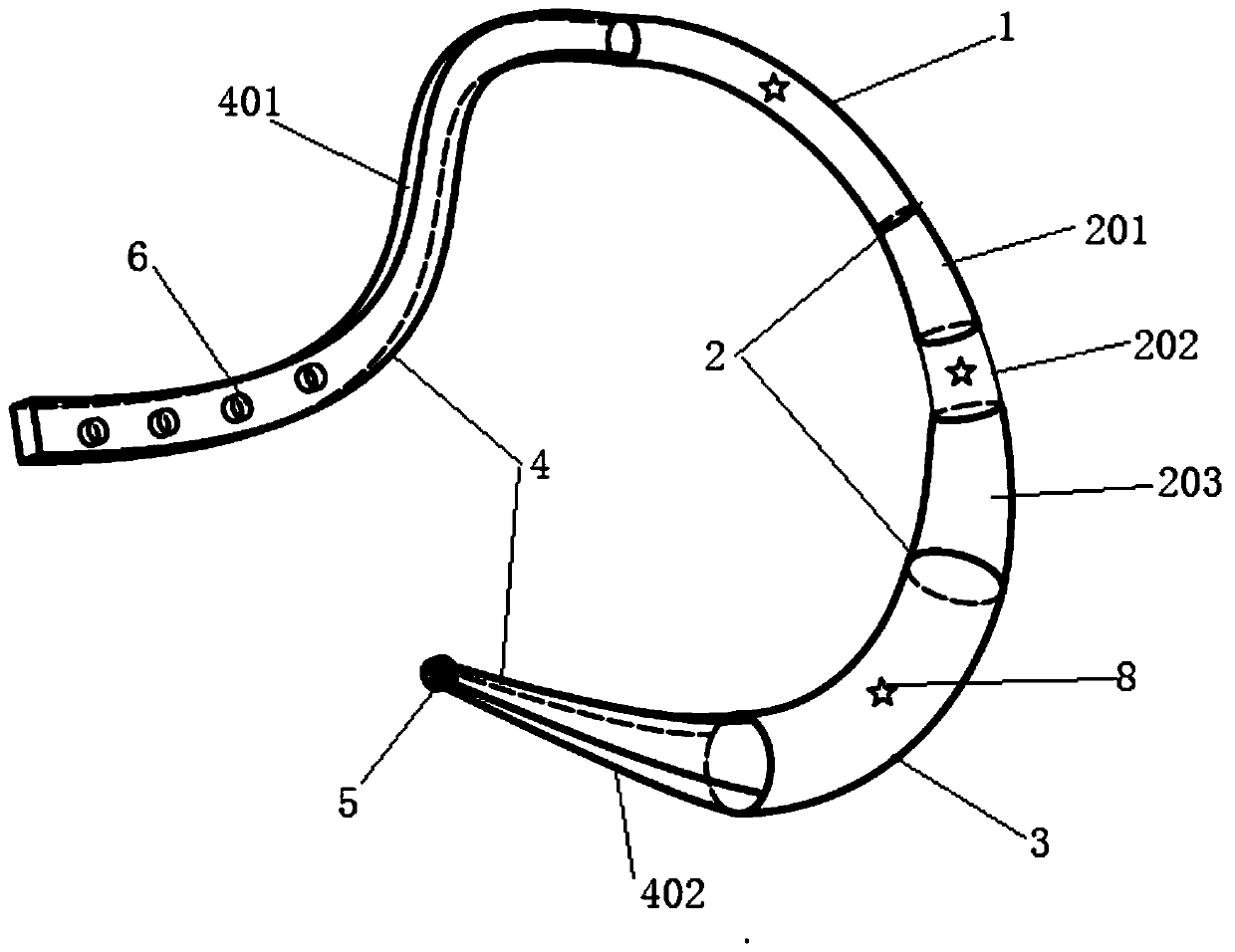
[0051] Such as image 3 As shown, the present embodiment provides a compressor for preventing PICC cannulation of internal jugular vein ectopy, including:

[0052] No. I compression column 1, No. II compression column 2 and No. III compression column 3, the first end of the No. I compression column 1 forms a free end, and the second end of the No. I compression column 1 is connected to the No. II compression column. The first end of the column 2 is fixedly connected, the first end of the No. III compression column 3 is fixedly connected with the second end of the No. II compression column 2, and the second end of the No. III compression column 3 forms a free end, Thus the three are connected to each other and form an arc-shaped structure;

[0053] Elastic band 4, described elastic band 4 comprises No. 1 elastic band 401 and No. 2 elastic band 402, described No. 1 elastic band 401 is detachably connected with the free end of described No. I compression column 1, described No. ...

Embodiment 3

[0061] This embodiment provides a method for operating the device of the present invention, and the specific steps are as follows:

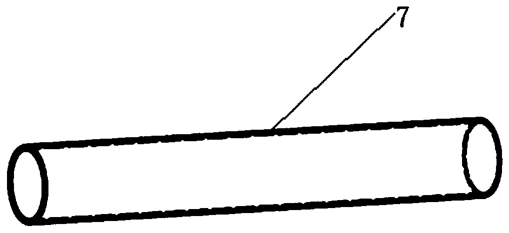
[0062] First evaluate the patient who needs to be placed in the PICC, evaluate the body shape, and select a suitable compression column based on this; then evaluate the neck circumference, determine the position where the elastic band 4 and the button 5 are combined, in principle, compared with the normal neck The girth is 2-4cm, which can not only play a fixed role, but also avoid the discomfort of the patient caused by excessive tightness. Put the disposable protective overcoat 7 over the entire compressor. Finally, put the compressor on the patient's neck, and ensure that the selected compression column is facing the position of the internal jugular vein. When the PICC catheter is placed, insert the catheter to 15cm, and instruct the patient to turn his head and squeeze the compression column. The pressure sensor built into the compression co...


PUM

PropertyMeasurementUnit
Diameteraaaaaaaaaa
Diameteraaaaaaaaaa
Lengthaaaaaaaaaa

Abstract

The invention relates to a compressor for preventing jugular phlebectopia of peripherally inserted central catheter (PICC). The compressor comprises a compression column I, a compression column II anda compression column III, wherein the first end of the compression column I is fixedly connected with the first end of the compression column II; the first end of the compression column III is fixedly connected with the second end of the compression column II, and the three compression columns are mutually connected to form a circular arc or elliptical arc structure. The compressor also compriseelastic belts, wherein the elastic belts comprise a first elastic belt and a second elastic belt; the first elastic belt is fixedly connected or detachably connected with the free end of the compression column I, the second elastic belt is fixedly connected or detachably connected with the free end of the compression column III, the first elastic belt is provided with elastic belt holes, and the second elastic belt is provided with a button. When the device is used, another PICC specialist nurse or a nurse with ultrasonic capability is not required for cooperation, so that waste of labor costis avoided.

Description

technical field [0001] The invention relates to a compressor for preventing the dislocation of the internal jugular vein with a PICC catheter, and belongs to the technical field of medical devices. Background technique [0002] Peripherally inserted central catheter (PICC) is mainly used for medium and long-term infusion and infusion of stimulant drugs. It is one of the safest infusion tools at present, for critically ill patients with anti-inflammatory drugs and neurological and surgical patients with poor venous conditions and relatively long treatment cycle. The 2016 edition of the Infusion Nursing Society guidelines pointed out that the tip of the PICC catheter should be located at the superior vena cava-atrium junction (CAJ) between the superior vena cava and the right atrium (CAJ) or the lower segment of the superior vena cava near the CAJ. , but due to the differences in the patient's physique, condition, and vascular status, catheter ectopy is a common complication ...

Claims


Application Information

Patent Timeline
IPC IPC(8): A61M25/01
CPCA61M25/01
Inventor 段丽娟王淑芹张萌胡晓科赵路
Owner BEIJING CHAOYANG HOSPITAL CAPITAL MEDICAL UNIV
Learn More