
Stiffening ring welding device for large penstock

A penstock and welding device technology, applied in auxiliary devices, welding equipment, auxiliary welding equipment, etc., can solve the problems of long fillet weld length of a single steel pipe, inability to weld steel pipes, and turning over of steel pipes

Pending Publication Date: 2020-07-03
SINOHYDRO ENG BUREAU 4
View PDF0 Cites 7 Cited by
  • Summary
  • Abstract
  • Description
  • Claims
  • Application Information

AI Technical Summary

Problems solved by technology

The length of the fillet weld of a single steel pipe is relatively long. If the traditional electrode arc welding method is used, it will take a long time and require a lot of manpower and material resources, which will easily cause the problem of delaying the production progress of the pressure steel pipe.
[0004] In the production process of large pressure steel pipes, the use of submerged arc welding to weld the stiffening ring fillet welds is widely used in actual production, but in the process of using submerged arc welding to weld the fillet welds of large pressure steel pipes, there are some problems to varying degrees , for example, it is necessary to weld both sides of the stiffening girth weld during the welding process, which means that the steel pipe must be turned over during the welding process
In addition, in the production process of the penstock steel pipe, the stiffened ring fillet weld is obliquely welded, and the welding quality cannot be effectively guaranteed. Furthermore, the conventional positioner device cannot weld steel pipes with a tonnage of 20t and a diameter of about 6m.

Method used


Image

  • Stiffening ring welding device for large penstock
  • Stiffening ring welding device for large penstock
  • Stiffening ring welding device for large penstock

Examples


Embodiment

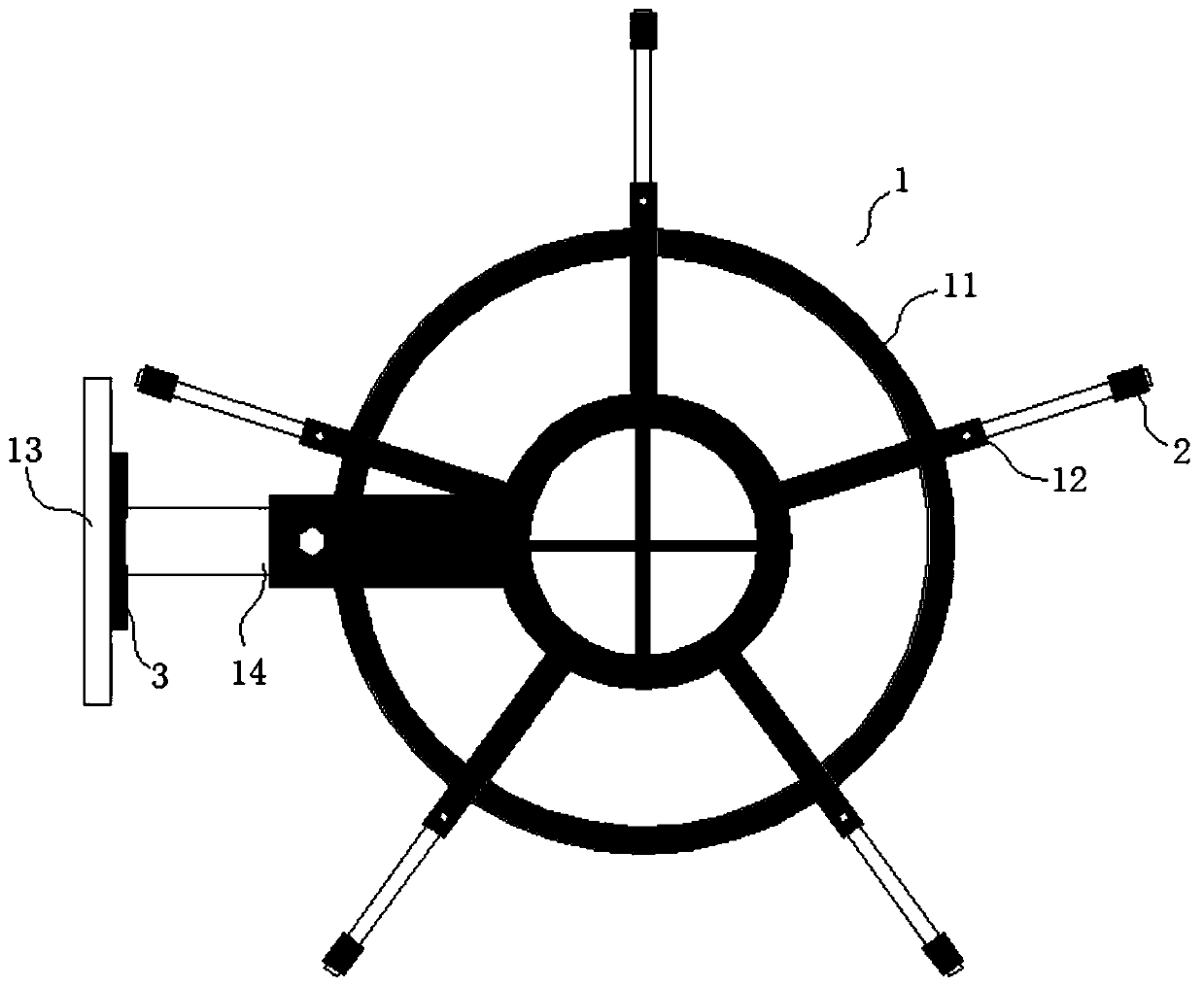
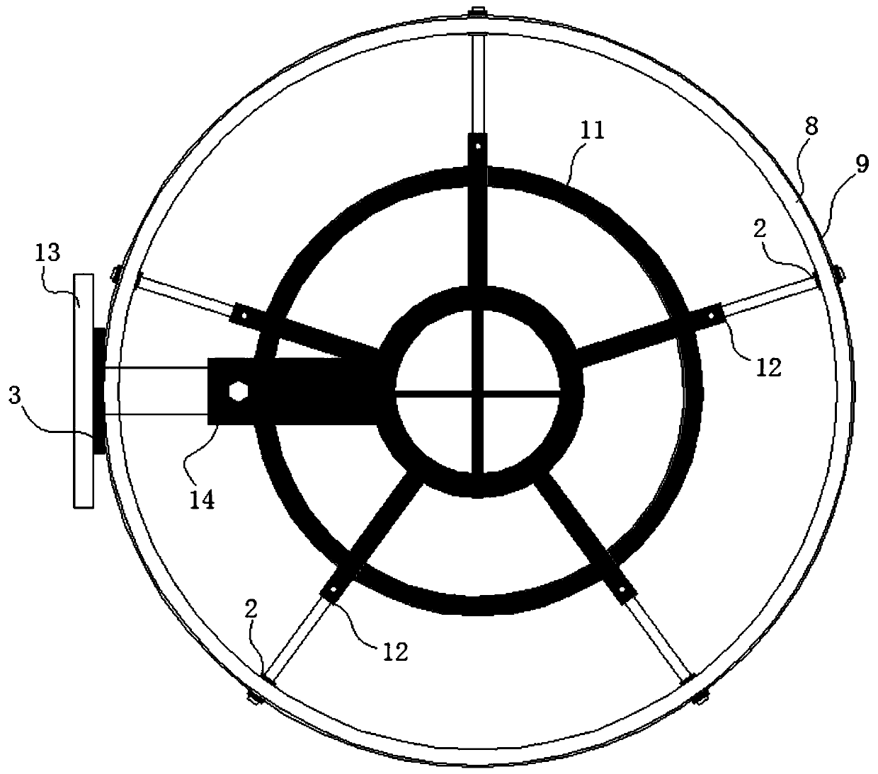
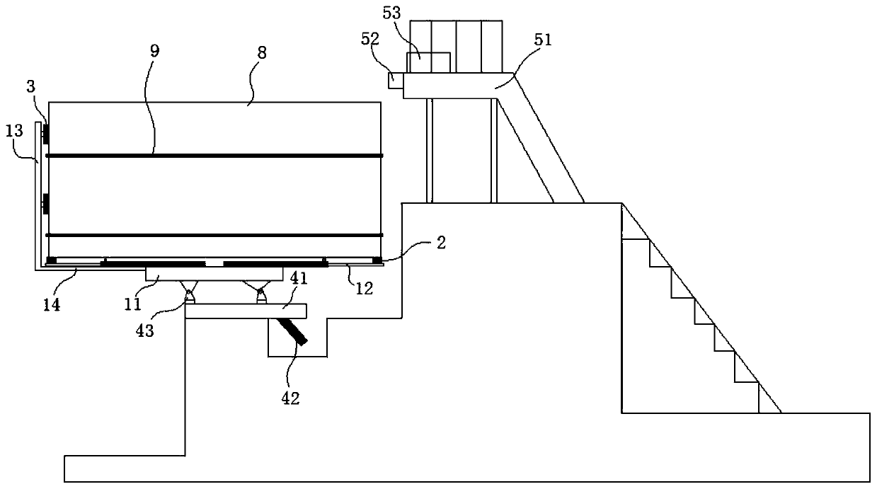
[0030] see figure 1 , figure 2 , image 3 , Figure 4 , a large pressure steel pipe stiffening ring welding device provided by the embodiment of the present invention, such as figure 1 , figure 2 , image 3 , Figure 4 As shown, the device includes a support frame 1, and the support frame 1 includes a connected horizontal part and a vertical part; the horizontal part includes an annular fixing part 11 and a plurality of brackets connected with the annular fixing part 11 and arranged radially Roller telescopic arms 12, each of the roller telescopic arms 12 is respectively provided with idler rollers 2, and the idler rollers 2 are used to abut against the end faces of the pressure steel pipes 8 so as to support the pressure steel pipes 8; the vertical The part 13 is connected with the annular fixing part 11 through the telescopic arm 14 of the vertical part; the horizontal part and the vertical part of the support frame provided by the application all have a telescopic s...


PUM


Abstract

The invention discloses a stiffening ring welding device for a large penstock. The welding device comprises a supporting frame, wherein the supporting frame comprises a horizontal part and a verticalpart which are connected to each other; and the horizontal part comprises an annular fixing part and a plurality of carrier roller telescopic arms which are connected with the annular fixing part andarranged in a radial mode, each of the carrier roller telescopic arms is provided with a carrier roller, and the carrier rollers are used for being connected with the end face of a penstock in an abutting mode so as to support the penstock. The device is composed of a hydraulic oil cylinder, a roller frame, the self-made carrier rollers and the like, other steel structures are assembled through equipment and tools in a steel pipe factory, the site construction condition is reasonably considered at the beginning of design, and the device is stable and reliable in the steel pipe turnover process. In the welding process, the welding speed can be effectively increased, the overturning working condition is completed through the hydraulic oil cylinder, the rotating working condition is completedthrough cooperation between the roller frame and the carrier rollers, and the device can be overturned and rotated. The device can be suitable for penstocks with different diameters.

Description

technical field [0001] The invention relates to the technical field of welding auxiliary equipment, in particular to a large pressure steel pipe stiffening ring welding device. Background technique [0002] In recent years, with the rapid development of my country's social economy, the scale of the power grid has continued to expand, and the peak-shaving capacity of the traditional thermal power grid is lacking. In response to the requirements of the economic operation of the national grid and the adjustment of the grid structure, the rapid development of emerging energy has accelerated the high-head pumped storage. Power station construction. Penstock water diversion is a relatively common water diversion method used in the construction of pumped storage power stations. During the water diversion process, all the water heads of the hydropower station are concentrated, the slope is steep, and the internal water pressure is high. The buried penstock pipes are designed and arra...

Claims


Application Information

Patent Timeline
IPC IPC(8): B23K37/047B23K37/053
CPCB23K37/047B23K37/053B23K37/0531
Inventor 龚锋滕泽环刘华云张克强闫琦周营坤赵锐峰梁志强
Owner SINOHYDRO ENG BUREAU 4
Learn More