
Aviation steel pipe polishing device

A steel pipe and aviation technology, which is applied in the field of aviation steel pipe grinding devices, can solve the problems of low grinding efficiency, poor cleaning, dust residue, etc., and achieve the effects of improving grinding efficiency, improving operating efficiency, and efficient suction and collection

Inactive Publication Date: 2020-07-03
重庆康铖智汇机械制造有限公司
View PDF5 Cites 7 Cited by
  • Summary
  • Abstract
  • Description
  • Claims
  • Application Information

AI Technical Summary

Problems solved by technology

[0002] The traditional steel pipe needs to be polished to keep the inner wall of the steel pipe flat. The traditional grinding device needs to use different equipment to grind the inner wall and outer wall of the steel pipe respectively. to clean up

Method used


Image

  • Aviation steel pipe polishing device
  • Aviation steel pipe polishing device
  • Aviation steel pipe polishing device

Examples


Embodiment 1

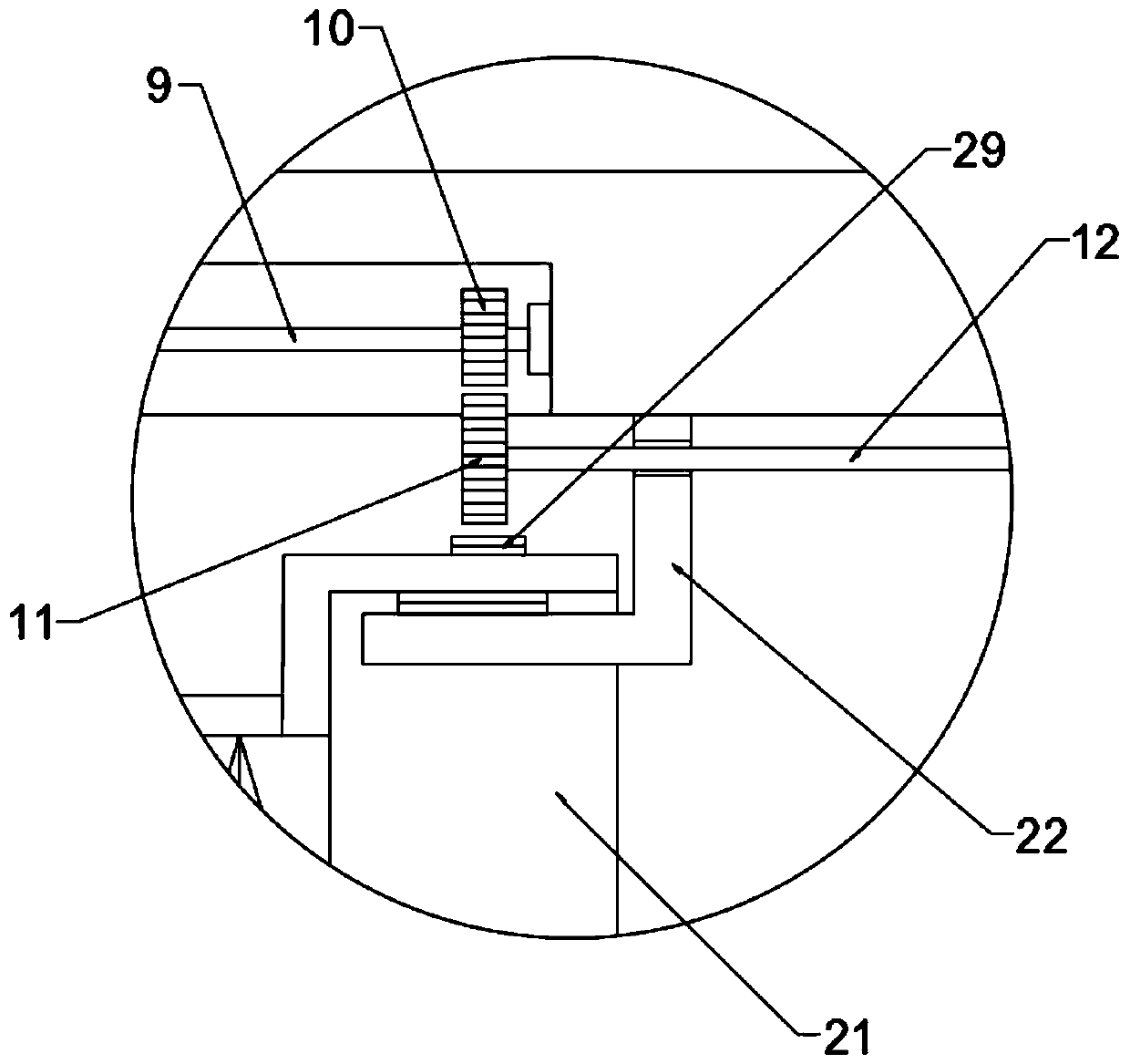
[0021] see Figure 1-4 , In an embodiment of the present invention, an aviation steel pipe grinding device includes a box body 1, a moving clamping mechanism and a grinding mechanism.

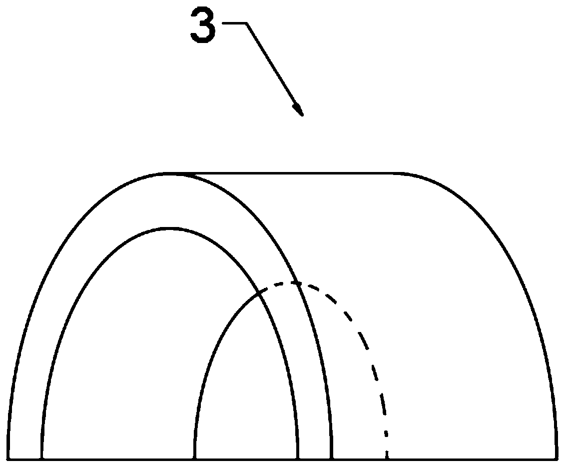
[0022] Described mobile clamping mechanism comprises moving plate 2, and one side of moving plate 2 is provided with a group of clamping plates 3 that are arranged symmetrically, and clamping plate 3 is arc-shaped plate, and clamping plate 3 is provided with arc-shaped groove, is convenient to The steel pipe is clamped; one end of the clamping plate 3 is nested in the moving plate 2, the moving plate 2 is provided with a vertical chute, the moving plate 2 is provided with a two-way screw rod 4, and the two-way screw rod 4 runs through the clamping plate 3 and is threadedly connected with the clamping plate 3; the two-way screw rod 4 is sleeved with a worm gear 5, the worm gear 5 is engaged with a worm 6, and the worm 6 extends to the outside of the moving plate 2 and is fixedly connected with a...

Embodiment 2

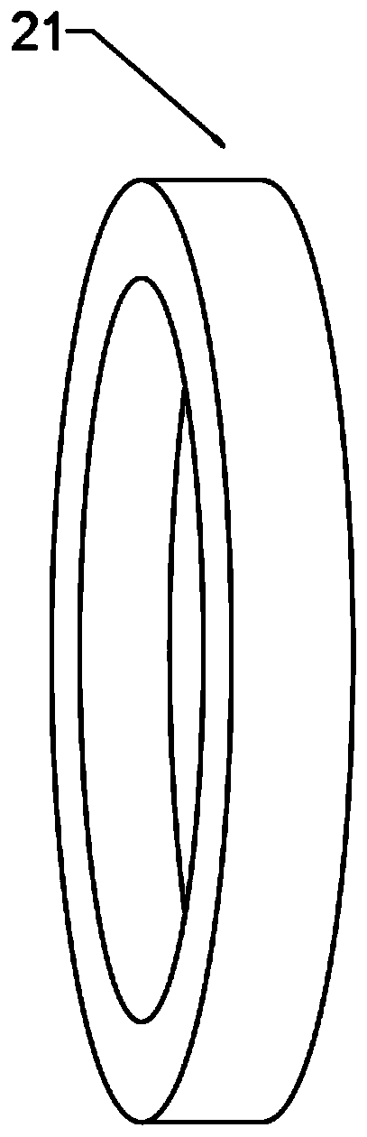
[0025] The difference between this embodiment and Embodiment 1 is that: the box body 1 is provided with a dust collection mechanism, the dust collection mechanism includes a blower 27, the blower 27 is connected with an air inlet pipe 26, the second rotating shaft 14 and the grinding shaft 18 are both hollow Pipe, the grinding shaft 18 is provided with evenly distributed air holes 29, the air inlet pipe 26 communicates with the second rotating shaft 14 through the rotary joint, the second rotating shaft 14 communicates with the grinding shaft 18, and the airflow generated by the blower 27 enters through the second rotating shaft 14 Grind the shaft 18 and discharge it from the air hole 29, and then blow the dust generated by the grinding of the inner wall of the steel pipe out of the steel pipe, so as to realize the rapid cleaning of the inner wall of the steel pipe; the grid plate 24 of the bottom plate of the box body 1 is provided with a collection tank below the grid net 24 ...


PUM


Abstract

The invention discloses an aviation steel pipe polishing device. The aviation steel pipe polishing device comprises a box body, a movable clamping mechanism and a polishing mechanism, wherein the movable clamping mechanism comprises a movable plate, and a set of symmetrically arranged clamping plates are arranged on one side of the movable plate; and the polishing mechanism comprises an inner polishing assembly and an outer polishing assembly. By arranging the movable clamping mechanism including the movable plate, the clamping plates, a worm wheel, a worm, an adjusting wheel, a movable blockand a lead screw, fast clamping and movable feeding of a steel pipe are realized; by arranging the polishing mechanism including a polishing shaft, a polishing plate, brush bristles and a polishing brush connected with a rotating cylinder, synchronous polishing of the inner wall and the outer wall of the steel pipe is achieved, and the polishing efficiency is improved; and by arranging a dust collecting mechanism including air holes formed in the polishing shaft, an air blower, a grid plate and a collecting tank, blast cleaning of the inner wall of the steel pipe and efficient suction collection of external dust are realized, the working environment is protected, and the working efficiency is improved.

Description

technical field [0001] The invention relates to the field of aviation steel pipe processing equipment, in particular to an aviation steel pipe grinding device. Background technique [0002] The traditional steel pipe needs to be polished to keep the inner wall of the steel pipe flat. The traditional grinding device needs to use different equipment to grind the inner wall and outer wall of the steel pipe respectively. clean up. [0003] The application provides an aviation steel pipe grinding device, which can simultaneously grind the inner and outer walls of the steel pipe and clean the remaining dust in the steel pipe. Contents of the invention [0004] The object of the present invention is to provide an aviation steel pipe grinding device to solve the problems raised in the above-mentioned background technology. [0005] To achieve the above object, the present invention provides the following technical solutions: [0006] An aviation steel pipe grinding device, comp...

Claims


Application Information

Patent Timeline
Patent Type & Authority Applications(China)
IPC IPC(8): B24B5/12B24B41/02B24B41/06B24B55/06
CPCB24B5/12B24B41/02B24B41/067B24B55/06
Inventor 车晨宇
Owner 重庆康铖智汇机械制造有限公司
Features
  • Generate Ideas
  • Intellectual Property
  • Life Sciences
  • Materials
  • Tech Scout
  • Unparalleled Data Quality
  • Higher Quality Content
  • 60% Fewer Hallucinations
Learn More