Environment-friendly oilfield sewage treatment device

A treatment device and technology for oilfield sewage, applied in biological water/sewage treatment, water/sewage multi-stage treatment, water/sludge/sewage treatment, etc., can solve the problem of single treatment method, achieve good effect and sludge treatment Thorough, effect-boosting effect

Inactive Publication Date: 2020-07-03
宋凯
View PDF8 Cites 4 Cited by
  • Summary
  • Abstract
  • Description
  • Claims
  • Application Information

AI Technical Summary

Problems solved by technology

[0004] The purpose of the present invention is to provide an environmental protection oilfield sewage treatment device to solve the problem of single treatment method proposed in the above background technology

Method used


Image

  • Environment-friendly oilfield sewage treatment device
  • Environment-friendly oilfield sewage treatment device
  • Environment-friendly oilfield sewage treatment device

Examples


Embodiment 1

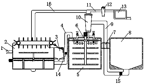
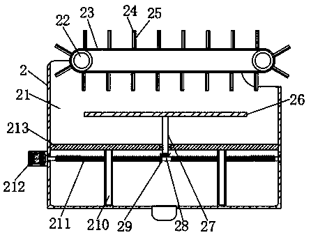
[0028] see Figure 1-8, an embodiment 1 provided by the present invention: an environment-friendly oilfield sewage treatment device, including a liquid inlet pipe 1, a first treatment device 2 is fixedly connected to the right side of the liquid inlet pipe 1, and the first treatment device 2 includes a treatment tank 21 , the first rotating shaft 22, connecting belt 23, scraper 24, oil-absorbing cloth 25, stirring rod 26, first connecting rod 27, first conical wheel 28, second conical wheel 29, push plate 210, screw rod 211, the first A motor 212 and a fixed rod 213, the left side surface of the processing box 21 is fixedly equipped with a first motor 212, and the output end of the first motor 212 is fixedly connected with a screw rod 211, and the surface of the screw rod 211 is sleeved with a push plate 210, and pushes The surface of the plate 210 is inserted in the inside of the fixed rod 213, the two sides of the fixed rod 213 are fixed on the inner wall of the processing b...

Embodiment 2

[0033] Embodiment 2: An environment-friendly oilfield sewage treatment device, including a liquid inlet pipe 1, a first treatment device 2 is fixedly connected to the right side of the liquid inlet pipe 1, and the first treatment device 2 includes a treatment box 21, a first rotating shaft 22, a connection Belt 23, scraper 24, oil-absorbing cloth 25, stirring rod 26, first connecting rod 27, first conical wheel 28, second conical wheel 29, push plate 210, screw rod 211, first motor 212 and fixed rod 213 , the left side surface of the processing box 21 is fixedly installed with a first motor 212, and the output end of the first motor 212 is fixedly connected with a screw rod 211, and the surface of the screw rod 211 is provided with two groups of external threads, and the direction of the external threads is opposite, which is convenient for two The group of push plates 210 are close to or far away from each other. The surface of the screw rod 211 is sleeved with the push plate ...


PUM


Abstract

The invention discloses an environment-friendly oilfield sewage treatment device. The device comprises a liquid inlet pipe, the right side of the liquid inlet pipe is fixedly connected with a first treatment device; an oil removal device is fixedly connected to the top end of the right side of the first treatment device; the bottom end of the first treatment device is connected with a fifth connecting pipe through a sixth connecting pipe; the right side of the first treatment device is connected with a reaction device through a first connecting pipe, a water pump is installed in the first connecting pipe, the inner wall of the top end of the reaction device is fixedly connected with a connecting device, the right side of the reaction device is connected with a sedimentation tank through asecond treatment device, and the bottom end of the sedimentation tank is fixedly connected with a vertical connecting pipe. Due to the arrangement of the second connecting pipe and a third connectingpipe, the sewage treatment modes are diversified, the sewage treatment effect is greatly improved through multiple treatment methods, the water treatment efficiency is greatly improved, the water quality is greatly improved, the floating oil removal effect is good through repeated use of oil absorption cloth, and sludge treatment is more thorough.

Description

technical field [0001] The invention relates to the technical field of sewage treatment equipment, in particular to an environmental protection oilfield sewage treatment device. Background technique [0002] With the development of society, the oil field is the sum of the oil and gas reservoirs in the same oil and gas producing area. The composition of the oil field sewage is relatively complex, and the oil content and the form of oil in the water are also different. The oil field sewage needs a lot of equipment for treatment. [0003] Existing patent number: CN201520276929.7 discloses an oilfield sewage treatment device, which includes a water inlet pipe connected to the bottom of the oil collection tank, and a dissolved air pump at the bottom of the oil collection tank extends into the lower part of the water inlet pipe of the oil collection tank through the dissolved air tank. There is a scraper machine on the top of the oil pool, and an oil storage tank on one side of th...

Claims


Application Information

Patent Timeline
Patent Type & Authority Applications(China)
IPC IPC(8): C02F9/14C02F101/32
CPCC02F1/40C02F1/52C02F3/02C02F3/34C02F9/00C02F2101/32
Inventor 宋凯
Owner 宋凯
Why Eureka
Try Eureka