
Automatic pressure dividing double gear pump

A duplex gear pump, automatic technology, applied in the direction of rotary piston/oscillating piston pump components, pump control, pump components, etc., can solve the problem of adjusting the output liquid flow rate, reducing the working effect of the gear pump, and affecting the use of the gear pump Effect and other issues, to achieve the effect of increasing friction, improving work effect, and increasing the effect of card setting

Inactive Publication Date: 2020-07-03
天津行走液压机械股份有限公司
View PDF0 Cites 0 Cited by
  • Summary
  • Abstract
  • Description
  • Claims
  • Application Information

AI Technical Summary

Problems solved by technology

[0004] 1. During the working process of the existing gear pump, the outlet pipe of the gear pump cannot adjust the flow rate of the output liquid according to the specific situation, thereby reducing the working effect of the gear pump and failing to meet the subsequent work requirements
[0005] 2. The existing gear pump is prone to vibration due to work during the working process, which affects the overall use effect of the gear pump and reduces the working performance of the gear pump

Method used


Image

  • Automatic pressure dividing double gear pump
  • Automatic pressure dividing double gear pump
  • Automatic pressure dividing double gear pump

Examples


Embodiment Construction

[0020] The following will clearly and completely describe the technical solutions in the embodiments of the present invention with reference to the accompanying drawings in the embodiments of the present invention. Obviously, the described embodiments are only some, not all, embodiments of the present invention. Based on the embodiments of the present invention, all other embodiments obtained by persons of ordinary skill in the art without making creative efforts belong to the protection scope of the present invention.

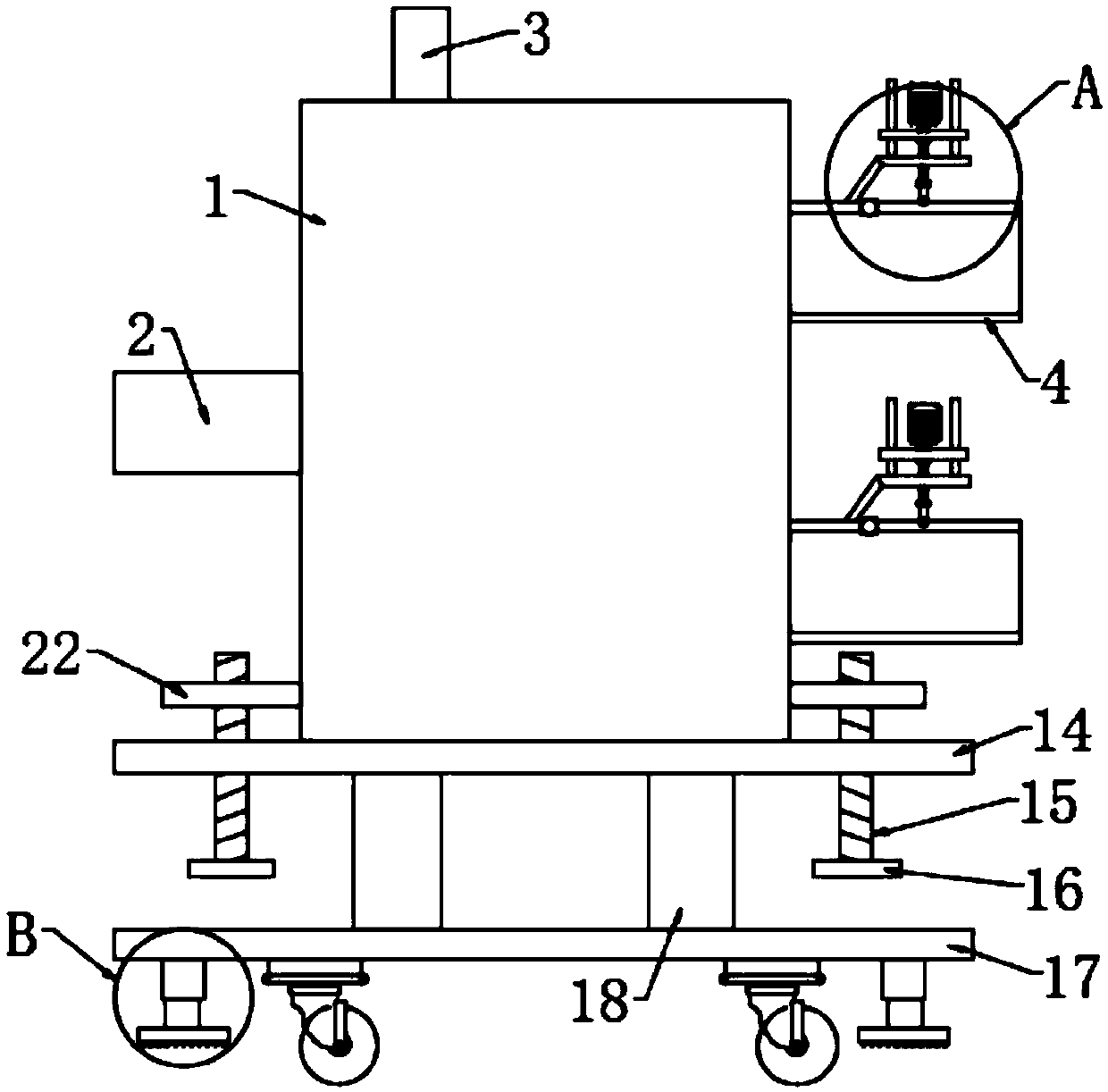
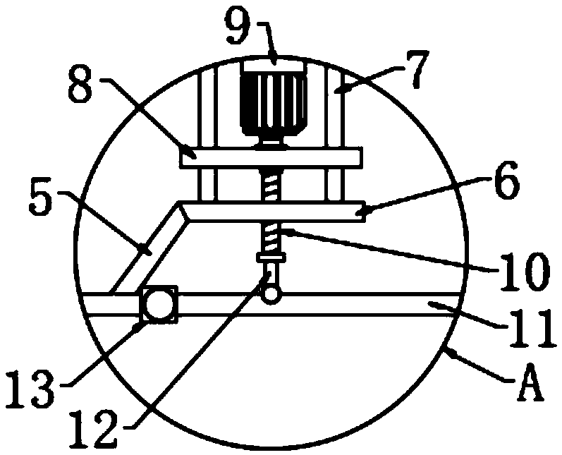
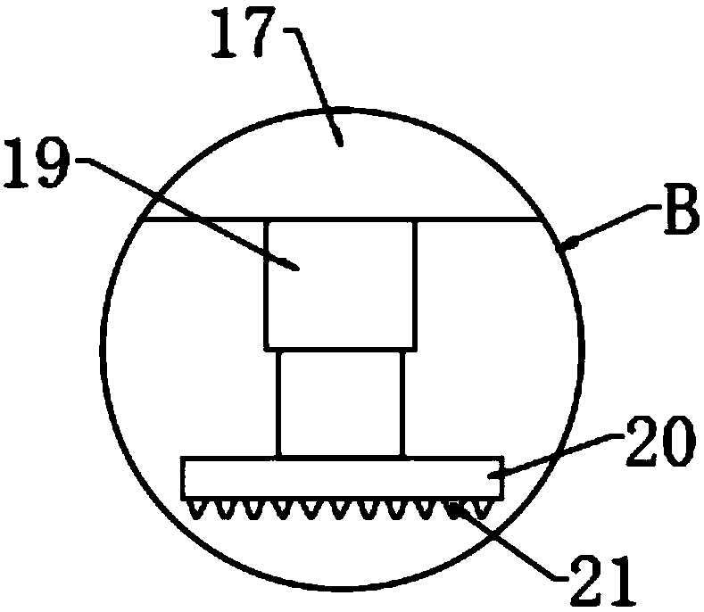
[0021] see Figure 1-3 , the present invention provides a technical solution: an automatic pressure-dividing double gear pump, including a pump body 1, a liquid inlet pipe 2 is fixedly arranged on one side of the pump body 1, and the top end of the pump body 1 passes through a mounting hole A rotating shaft 3 is installed, and both ends of the pump body 1 away from the liquid inlet pipe 2 are fixedly provided with a liquid outlet pipe 4, and the top end of the...


PUM


Abstract

The invention discloses an automatic pressure dividing double gear pump. The automatic pressure dividing double gear pump comprises a pump body, a liquid inlet pipe is fixedly arranged on one side ofthe pump body, a rotating shaft is installed at one end of the top of the pump body through an installation hole, liquid outlet pipes are correspondingly and fixedly arranged at two ends of the side,away from the liquid inlet pipe, of the pump body, connecting plates are fixedly arranged at one ends of the tops of the liquid outlet pipes, first supporting plates are fixedly arranged at the ends,away from the liquid outlet pipes, of the connecting plates, a plurality of sliding rods are uniformly arranged at the two ends of the tops of the first supporting plates, second supporting plates arefixedly arranged between the ends, away from the first supporting plates, of the multiple sliding rods, motors are installed at the tops of the second supporting plates through installation seats, first screw rods are movably arranged at the bottoms of the second supporting plates, and the output shaft ends of the motors are connected with the first screw rods through coupling devices in a transmission mode. According to the automatic pressure dividing double gear pump, by changing the flow rate, the double gear pump can conduct conveying work according to the specific situation, the workingeffect of the gear pump is improved, and the subsequent process of conveying liquid is facilitated.

Description

technical field [0001] The invention relates to the technical field of gear pumps, in particular to an automatic pressure dividing double gear pump. Background technique [0002] The gear pump is a rotary pump that relies on the change and movement of the working volume formed between the pump cylinder and the meshing gear to deliver or pressurize the liquid. [0003] Existing gear pumps have the following deficiencies: [0004] 1. During the working process of the existing gear pump, the outlet pipe of the gear pump cannot adjust the flow rate of the output liquid according to the specific situation, thereby reducing the working effect of the gear pump and failing to meet the subsequent work requirements. [0005] 2. The existing gear pump is prone to vibration during the working process, which affects the overall use effect of the gear pump and reduces the working performance of the gear pump. Contents of the invention [0006] The object of the present invention is to...

Claims


Application Information

Patent Timeline
Patent Type & Authority Applications(China)
IPC IPC(8): F04C14/00F04C15/06F04C15/00
CPCF04C14/00F04C15/00F04C15/06
Inventor 任强
Owner 天津行走液压机械股份有限公司
Learn More