
Carbonization furnace and carbonization incineration system

A carbonization furnace and combustion furnace technology, which is applied to incinerators, combustion methods, combustion types, etc., can solve the problems of increasing equipment volume, incomplete treatment, and difficult transportation, and achieve the effect of reducing volume, saving heat sources, and saving costs.

Inactive Publication Date: 2020-07-03
SHANGHAI LIANGHUI ENVIRONMENTAL PROTECTION MACHINERY
View PDF8 Cites 0 Cited by
  • Summary
  • Abstract
  • Description
  • Claims
  • Application Information

AI Technical Summary

Problems solved by technology

[0002] Household waste is generally collected and processed in a centralized manner, which brings about difficulties in transportation after collection, environmental pollution during transportation, and direct incineration is likely to cause environmental pollution, especially in the treatment of rural domestic waste after collection, on ships, etc. There is no dedicated safe and environmentally friendly treatment device for domestic waste treatment
Similarly, there are occasions where domestic waste is centrally disposed of in factories, living quarters, office buildings, rural areas, and ships. In particular, a safe and environmentally friendly carbonization incineration treatment suitable for domestic waste and materials similar to domestic waste is required to solve the problem of traditional small Handling of domestic waste treatment, environmental pollution, and incomplete treatment
[0003] The carbonization furnace in the prior art mainly uses electric energy for heating, that is, it needs to introduce an additional electric energy heating device, and at the same time increases the overall volume of the equipment

Method used


Image

  • Carbonization furnace and carbonization incineration system
  • Carbonization furnace and carbonization incineration system

Examples


Embodiment Construction

[0025] In order to better understand the present invention, the present invention will be further described below in conjunction with specific embodiments and accompanying drawings.

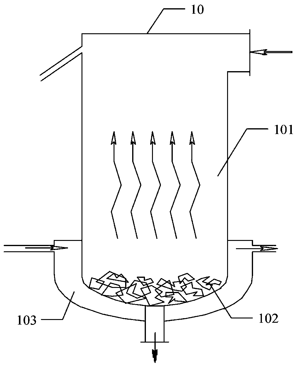
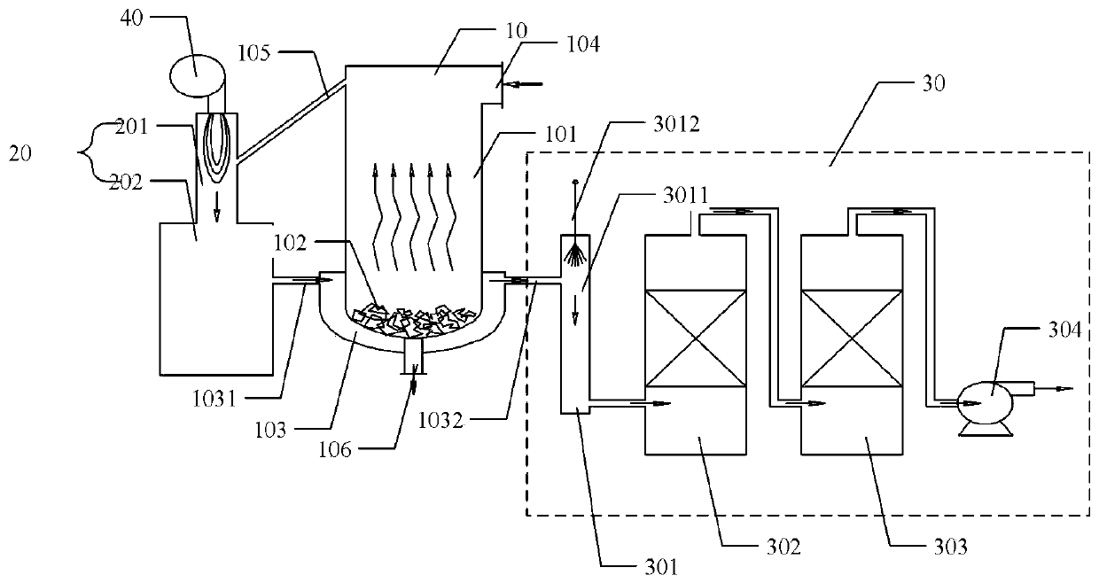
[0026] Such as figure 1 As shown, the present invention provides a carbonization furnace 10, the carbonization furnace 10 includes a carbonization furnace body 101, the carbonization furnace body 101 is a cavity placed vertically, and the outer wall of the cavity conducts heat; the carbonization furnace body 101 The bottom of the cavity is provided with a heat-conducting carbonization head 102;

[0027] In a specific embodiment of the present invention, the heating medium in the heating spacer 103 can be high-temperature gas, high-temperature liquid, etc. In specific applications, the heating medium in the heating spacer 103 can be drawn from high-temperature industrial The heat of waste gas or industrial waste water, high-temperature industrial waste gas and industrial waste water is transferre...


PUM


Abstract

The invention provides a carbonization furnace and a carbonization incineration system. The carbonization furnace comprises a carbonization furnace body, wherein the carbonization furnace body is a vertically placed cavity, the outer wall of the cavity conducts heat, a heat-conducting carbonization seal head is arranged at the bottom of the cavity of the carbonization furnace body, and the outer wall of the bottom of the carbonization furnace body is wrapped with a heating spacer bush used for containing a heating medium, so that heat is transmitted to the carbonization seal head. According tothe carbonization furnace, the heating spacer bush is arranged and used for containing the heating medium, so that high-temperature industrial wastewater or waste gas can be used as the heating medium, the high-temperature industrial wastewater or industrial waste gas is secondarily utilized, a heating device in a common carbonization furnace is replaced, and the high-temperature industrial wastewater or industrial waste gas is fully utilized; and in addition, the heat-conducting carbonization seal head is arranged in the carbonization furnace body, so that the heat can be fully concentratedon the carbonization seal head, heat gathering is facilitated, the carbonization seal head can make direct contact with an object to be carbonized, and the carbonization process is more thorough.

Description

technical field [0001] The invention relates to the technical field of domestic garbage incineration, in particular to a carbonization furnace and a carbonization incineration system. Background technique [0002] Household waste is generally collected and processed in a centralized manner, which brings about difficulties in transportation after collection, environmental pollution during transportation, and direct incineration is likely to cause environmental pollution, especially in the treatment of rural domestic waste after collection, on ships, etc. There is no special safe and environmentally friendly treatment device for domestic waste treatment. Similarly, there are occasions where domestic waste is centrally disposed of in factories, living quarters, office buildings, rural areas, and ships. In particular, a safe and environmentally friendly carbonization incineration treatment suitable for domestic waste and materials similar to domestic waste is required to solve t...

Claims


Application Information

Patent Timeline
Patent Type & Authority Applications(China)
IPC IPC(8): F23G5/027F23G5/16F23G5/08F23G5/44F23G5/46F23J15/06
CPCF23G5/0273F23G5/16F23G5/08F23G5/44F23G5/46F23J15/06F23G2201/302F23G2206/10Y02E20/30
Inventor 朱建华朱君亮
Owner SHANGHAI LIANGHUI ENVIRONMENTAL PROTECTION MACHINERY
Learn More