Optical fiber coupling device and laser coupling equipment

A technology of optical fiber coupling device and coupling equipment, which is applied in the field of optical fiber coupling, and can solve the problems of inconvenient cleaning, limited use range, and easily damaged optical fibers, etc.

Inactive Publication Date: 2020-07-03
SUZHOU EVERBRIGHT PHOTONICS CO LTD +1
View PDF5 Cites 1 Cited by
  • Summary
  • Abstract
  • Description
  • Claims
  • Application Information

AI Technical Summary

Problems solved by technology

[0005] Therefore, the technical problem to be solved by the present invention is to overcome the defects that the optical fiber coupling device in the prior art has a limited range of use and is not easy to clean up and easily damage the optical fiber, thereby providing a fiber coupling device and a laser coupling device

Method used


Image

  • Optical fiber coupling device and laser coupling equipment
  • Optical fiber coupling device and laser coupling equipment
  • Optical fiber coupling device and laser coupling equipment

Examples


Embodiment

[0044] This embodiment provides a laser coupling device, which includes a laser device, a laser shaper and a fiber coupling device. The laser device emits laser light that passes through the laser shaper and then inputs light into the input end of the fiber coupling device. The laser coupling device can be a semiconductor laser or others.

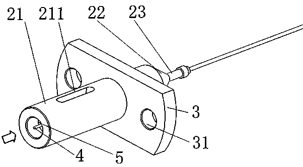
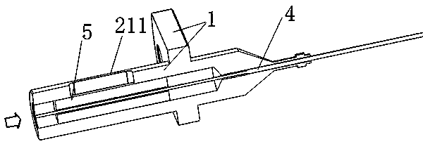
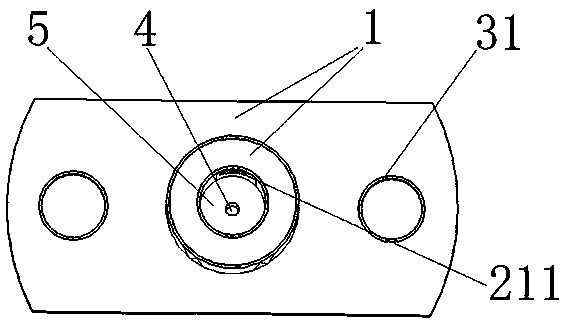
[0045] like Figure 1 to Figure 3 As shown, the fiber coupling device includes a heat-conducting housing 1 , a bare optical fiber 4 and a ferrule 5 . Among them, the bare optical fiber 4 is passed through the heat-conducting shell 1 for energy transmission; the ferrule 5 is located between the heat-conducting shell 1 and the bare optical fiber 4 to connect the heat-conducting shell 1 and the bare optical fiber 4, wherein the input of the ferrule 5 The ends are provided with reflective coatings. It should be noted that the input end of each component refers to the end of each component that is irradiated with light to input light.

[0046...


PUM

PropertyMeasurementUnit
reflectanceaaaaaaaaaa

Abstract

The invention discloses an optical fiber coupling device and laser coupling equipment. The optical fiber coupling device comprises a heat conduction shell, a bare optical fiber and an insertion core,wherein the bare optical fiber is arranged in the heat conduction shell in a penetrating mode and used for conducting energy transmission, and the input end of the heat conduction shell is flush withthe input end of the bare optical fiber; and the insertion core is located between the heat conduction shell and the bare optical fiber so as to connect the heat conduction shell and the bare opticalfiber, and the input end part of the insertion core is provided with a reflection plating layer. The input end of the heat conduction shell is flush with the input end of the bare optical fiber, the bare optical fiber can be cleaned in a non-contact mode, and cleaning airflow does not need to pass through the inner side wall of the heat conduction shell during cleaning, so that the bare optical fiber is cleaned conveniently, the service life of the bare optical fiber is ensured, and the cost is reduced at the same time; through the flush arrangement, the incident angle can be changed and is not limited by the wall surface of the heat conduction shell; and the reflection plating layer is arranged, so that the absorption of the insertion core to the light is reduced.

Description

technical field [0001] The invention relates to the technical field of optical fiber coupling, in particular to an optical fiber coupling device and laser coupling equipment. Background technique [0002] There are two main ways for the light emitted by the laser source to enter the bare fiber: direct coupling and lens coupling. Among them, lens coupling can obtain higher coupling efficiency than direct coupling. Lens coupling specifically means that the light emitted by the laser source is concentrated to the input end of the bare fiber through lens shaping, and energy transmission is realized through the bare fiber. [0003] The prior art discloses a laser transmitter module, which includes a ferrule assembly, a fiber core part of an optical fiber, and a fiber connection sleeve. The fiber core part of the optical fiber passes through the ferrule assembly for energy transmission; the fiber connection sleeve A tube is positioned between the ferrule assembly and the core po...

Claims


Application Information

Patent Timeline
Patent Type & Authority Applications(China)
IPC IPC(8): G02B6/42
CPCG02B6/4214G02B6/4239G02B6/4296
Inventor 陈磊潘华东廖新胜裘利平袁磊周军
Owner SUZHOU EVERBRIGHT PHOTONICS CO LTD
Why Eureka
Try Eureka