
Circuit model of lateral double-diffused transistor and modeling method thereof

A technology of horizontal double diffusion and circuit model, which is applied in the direction of CAD circuit design, etc., can solve the problems of poor simulation speed and convergence, slow down the speed of large-scale integrated circuit simulation, and large amount of calculation, so as to enhance usability and reliability, shorten Circuit design cycle, effect of improving precision and accuracy

Active Publication Date: 2020-07-03
JOULWATT TECH INC LTD
View PDF5 Cites 4 Cited by
  • Summary
  • Abstract
  • Description
  • Claims
  • Application Information

AI Technical Summary

Problems solved by technology

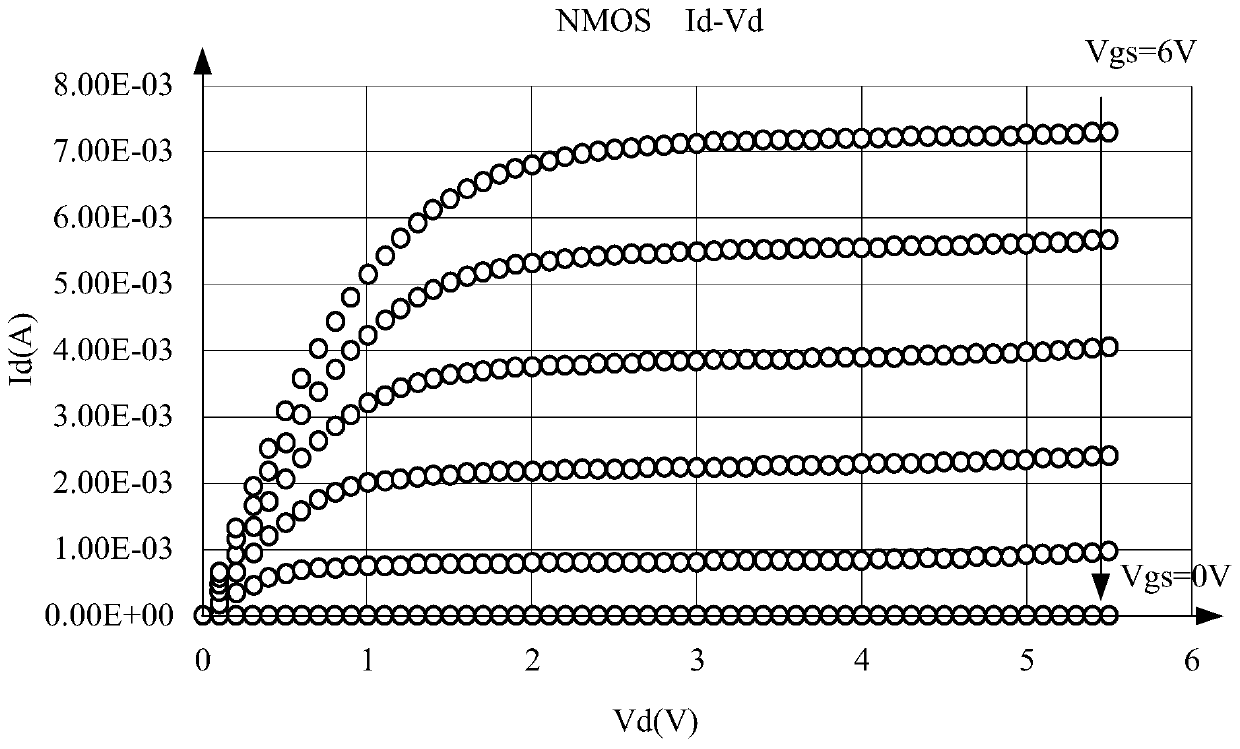
[0003] Currently, BSIM (Berkeley Short-channel IGFET Mode, Berkeley Short-channel Insulated Gate Field-Effect Transistor Model) is the most widely used transistor device model in the industry. The DC characteristics of MOSFET (Metal-Oxide-Semiconductor Field-Effect Transistor, Metal-Oxide Semiconductor Field-Effect Transistor), such as narrow channel effect, short channel effect, drain-induced barrier lowering effect, body effect, etc., and different sizes The MOSFET characteristics have certain predictive ability, but the BSIM4 model is not adapted for LDMOS devices. The original BSIM4 model cannot accurately characterize some unique device characteristics of LDMOS, such as quasi-saturation effect
[0004] Other device models used for LDMOS characteristic analysis, such as the Hisim_hv model and PSP model based on surface potential calculation, usually have a large amount of calculation, which will greatly slow down the speed of large-scale integrated circuit simulation; and the Verilog-A language is used for device characteristics. Macro model, poor simulation speed and convergence, cannot be applied on a large scale

Method used


Image

  • Circuit model of lateral double-diffused transistor and modeling method thereof
  • Circuit model of lateral double-diffused transistor and modeling method thereof
  • Circuit model of lateral double-diffused transistor and modeling method thereof

Examples


Embodiment Construction

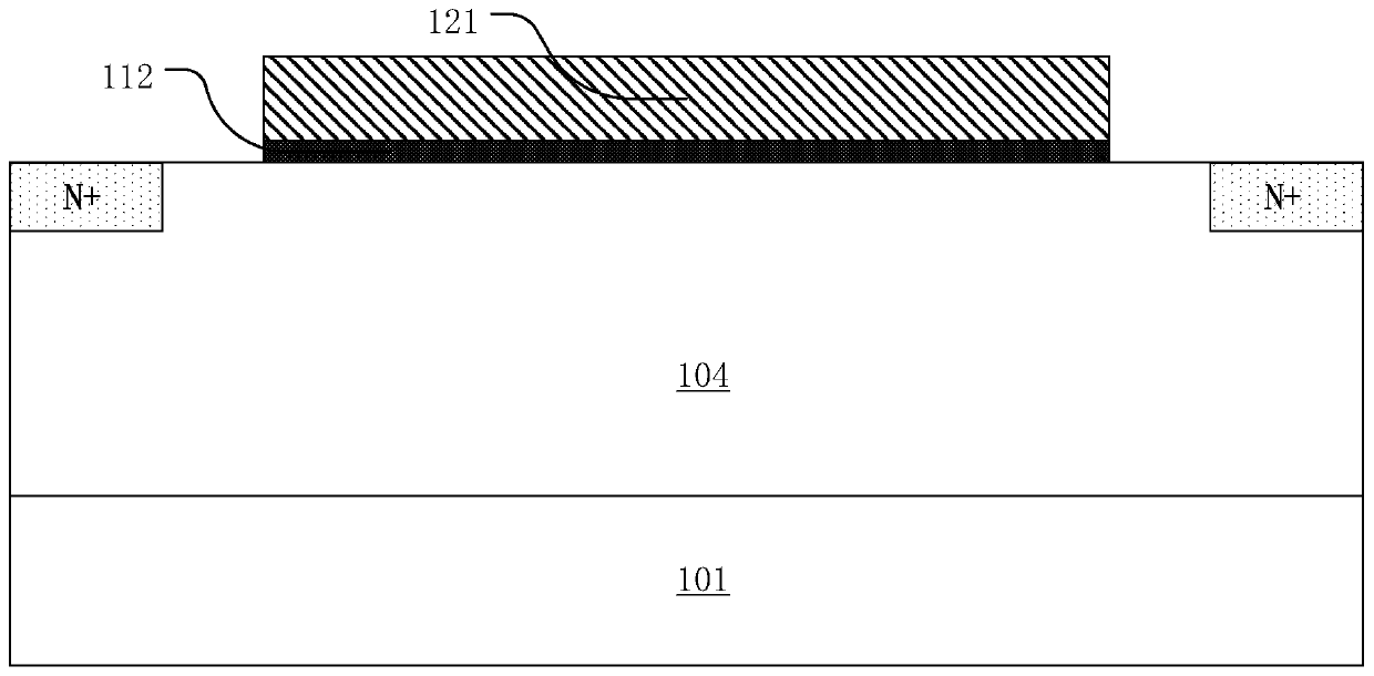
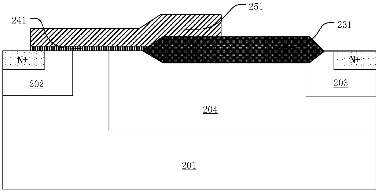
[0041] Various embodiments of the invention will be described in more detail below with reference to the accompanying drawings. In the various drawings, the same elements are denoted by the same or similar reference numerals. For the sake of clarity, various parts in the drawings have not been drawn to scale. Also, some well-known parts may not be shown. For the sake of simplicity, the semiconductor structure obtained after several steps can be described in one figure.

[0042] When describing the structure of a device, when a layer or a region is referred to as being "on" or "over" another layer or another region, it may refer to being directly above another layer or another region, or between it and Other layers or regions are also included between another layer and another region. And, if the device is turned over, the layer, one region, will be "below" or "beneath" the other layer, another region. If it is to describe the situation directly on another layer or another ...


PUM


Abstract

The invention discloses a circuit model of a lateral double-diffused transistor and a modeling method thereof. The circuit model comprises a standard BSIM4 model; a drift region equivalent resistor, wherein the drift region equivalent resistor comprises a plurality of resistance correction term coefficients and is used for correcting the resistance of the drift region, and the circuit model is used for representing the change characteristics of the saturation threshold voltage and the drain current of the lateral double-diffusion transistor. The LDMOS circuit model and the modeling method of the LDMOS circuit model are based on a BSIM4 model. Custom-made drift region equivalent resistance is added; the quasi-saturation effect in the LDMOS can be accurately represented; according to the circuit model, the convergence, compatibility and high simulation speed of the BSIM4 model are utilized, various characteristics of the LDMOS can be accurately represented, the circuit design period is shortened, and the problem that the BSIM model cannot accurately represent the characteristics of the LDMOS is solved.

Description

technical field [0001] The invention relates to the field of integrated circuits, in particular to a circuit model of a lateral double-diffusion transistor and a modeling method thereof. Background technique [0002] As a kind of power field effect transistor, LDMOS (Lateral Double-Diffused MOSFET) has been widely used in integrated circuits due to its excellent characteristics, and the accuracy of the LDMOS device model has become more and more important . In the LDMOS modeling process, the modeling of the drift region resistance is particularly important, and its accuracy will directly affect the simulation accuracy of the LDMOS device model under different working conditions. [0003] Currently, BSIM (Berkeley Short-channel IGFET Mode, Berkeley Short-channel Insulated Gate Field-Effect Transistor Model) is the most widely used transistor device model in the industry. The DC characteristics of MOSFET (Metal-Oxide-Semiconductor Field-Effect Transistor, Metal-Oxide Semicon...

Claims


Application Information

Patent Timeline
IPC IPC(8): G06F30/36
Inventor 蒋盛烽陆阳
Owner JOULWATT TECH INC LTD
Learn More