
Combination machining device for gas compressor stator component assembling

A combined processing and air compressor technology, applied in the direction of workpiece clamping devices, manufacturing tools, etc., can solve problems such as the inability to ensure the safety of the hoisting process, the inability to guarantee the quality of processing, assembly quality, and processing deviations

Active Publication Date: 2020-07-07
AECC AVIATION POWER CO LTD
View PDF6 Cites 0 Cited by
  • Summary
  • Abstract
  • Description
  • Claims
  • Application Information

AI Technical Summary

Problems solved by technology

[0003] In order to ensure the above design requirements, the compressor stator assembly needs to be assembled in a simulation according to the installed state. After assembly, it needs to be combined with the transfer case center and the research and development center for combined processing, and the transfer metering center for testing. The compressor stator assembly weighs about 90 kg. The large thin-walled easily deformable part with a total length of about 500mm and a diameter of about φ800mm, after repeated hoisting and transportation, its front and rear mounting edges are more likely to be bumped, damaged and deformed, resulting in difficulties in aligning benchmarks and processing deviations during combined processing and testing, and cannot guarantee processing quality and The final assembly quality of the whole machine increases the difficulty of processing and assembly. At present, it mainly relies on human control of the hoisting process, but it is still unable to ensure the safety of the hoisting process.

Method used


Image

  • Combination machining device for gas compressor stator component assembling
  • Combination machining device for gas compressor stator component assembling
  • Combination machining device for gas compressor stator component assembling

Examples


Embodiment Construction

[0023] The present invention is described in further detail below in conjunction with accompanying drawing:

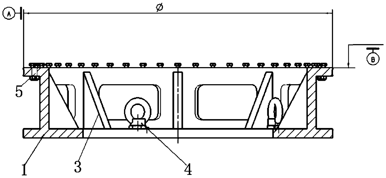
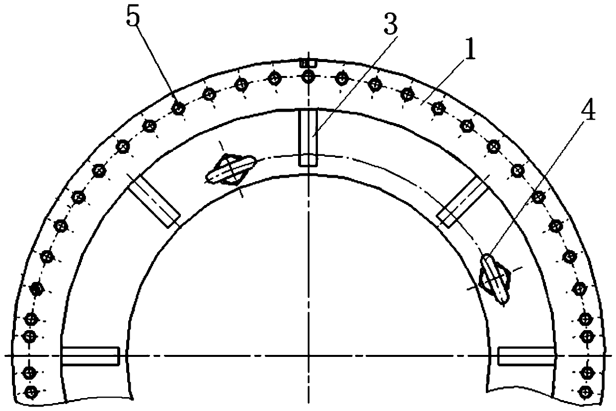
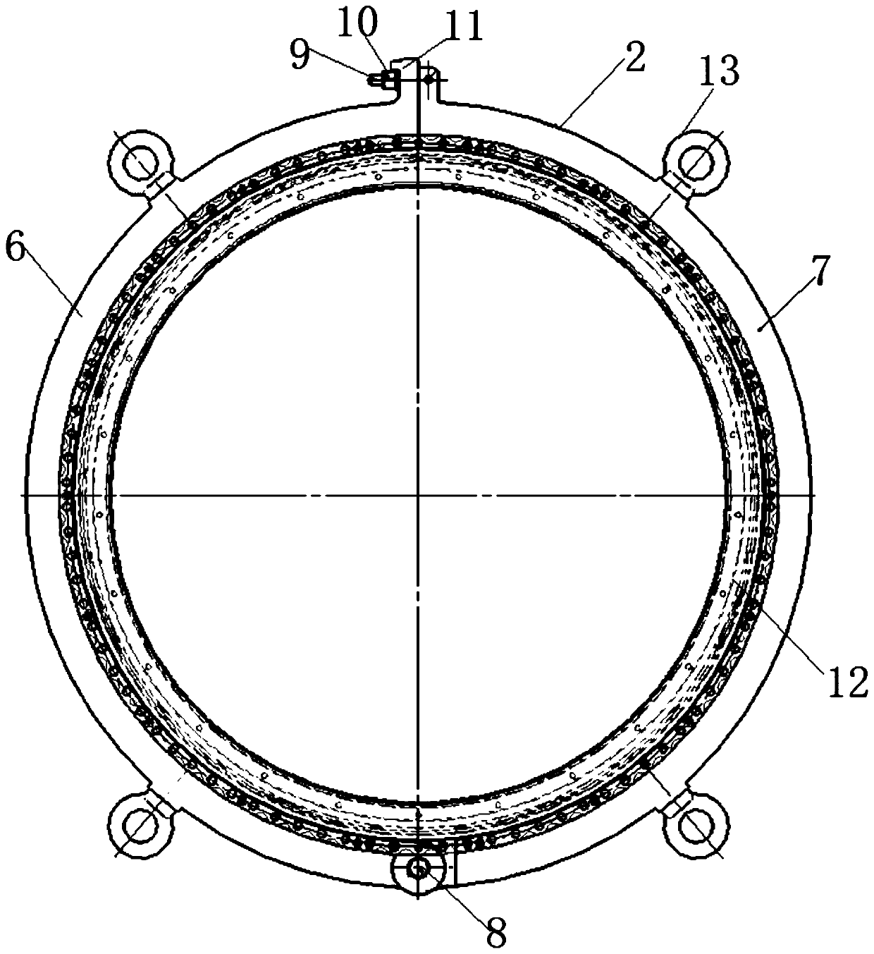
[0024] Such as figure 1 , figure 2 As shown, a combined processing device for assembling stator components of a compressor includes a positioning platform 1 and a seam fixture 2. The positioning platform 1 is an annular through-hole structure, and one side end surface of the positioning platform 1 is the front installation side end surface, which is used for It fits with the front mounting side and end face of the compressor stator assembly to be assembled and processed, and the bolt through hole 5 is set on the front mounting side and end face of the positioning platform 1, and the bolt through hole on the positioning platform 1 and the compressor stator to be assembled and processed The bolt holes on the front mounting side of the component are aligned, the compressor stator component and the positioning platform 1 are tightly connected by connecting bolts, and the...


PUM


Abstract

The invention discloses a combination machining device for gas compressor stator component assembling. A positioning platform and a spigot clamp are arranged; the positioning platform is attached to and fixedly connected with the front mounting edge end face of a gas compressor stator component to be subjected to assembling and combination machining; the spigot clamp is used for jointly clamping arear component and an inner component of the gas compressor stator component to be subjected to assembling and combination machining, thereby preventing a rear end spigot of the gas compressor statorcomponent from deforming; simultaneously, the positioning platform and the spigot clamp are respectively matched with the front mounting edge of the engine compressor stator component and the rear mounting edge of the engine compressor stator component, thereby realizing the requirements of one-time assembling and clamping of the gas compressor stator component for multiple different combinationmachining and detection as well as meeting the situation of ensuring the precision due to the process adjustment machining caused by production resource problems; the detection and combination machining of the front and rear end surfaces of the gas compressor stator component and an inner ring of a rectifier can be achieved; and meanwhile, the two benchmarks of the front mounting edge end face andthe front mounting edge pitch circle of the gas compressor stator component to be subjected to assembling and combination machining can be ensured to be unchanged in the processes of assembling, transferring, combination machining and detecting, and repeated assembling and disassembling of the gas compressor stator component is reduced.

Description

technical field [0001] The invention belongs to the technical field of assembling an engine compressor assembly, and in particular relates to a combined processing device for assembling an air compressor stator assembly. Background technique [0002] As a simulated assembly of the engine, the compressor stator assembly consists of a front-to-side open case, a center-to-open case, an inner casing, a rear casing, multi-stage guide vanes, multi-stage rectifiers and inner rings at various levels. According to the design requirements, the purpose of the first assembly of the compressor stator assembly is: combined grinding of honeycombs on the inner rings at all levels; combined inspection of the adjustable angle range of the guide vanes at all levels, and clamping and polishing; combined processing to ensure the overall axial length of the components and end face runout; check and process to ensure the distance from the front and rear end faces of the inner rings at all levels t...

Claims


Application Information

Patent Timeline
Patent Type & Authority Applications(China)
IPC IPC(8): B25B11/00
CPCB25B11/00
Inventor 王满贤李荣庞昕闫艳杨翠玲李亚高珺梅王瑀
Owner AECC AVIATION POWER CO LTD
Learn More