Hybrid power coupling system and vehicle

A technology of hybrid power and coupling system, which is applied to hybrid vehicles, motor vehicles, power plants, etc., and can solve problems such as lack of power and economy

Pending Publication Date: 2020-07-07
GUANGZHOU AUTOMOBILE GROUP CO LTD
View PDF0 Cites 4 Cited by
  • Summary
  • Abstract
  • Description
  • Claims
  • Application Information

AI Technical Summary

Problems solved by technology

[0008] The technical problem to be solved by the present i

Method used


Image

  • Hybrid power coupling system and vehicle
  • Hybrid power coupling system and vehicle
  • Hybrid power coupling system and vehicle

Examples


Embodiment 1

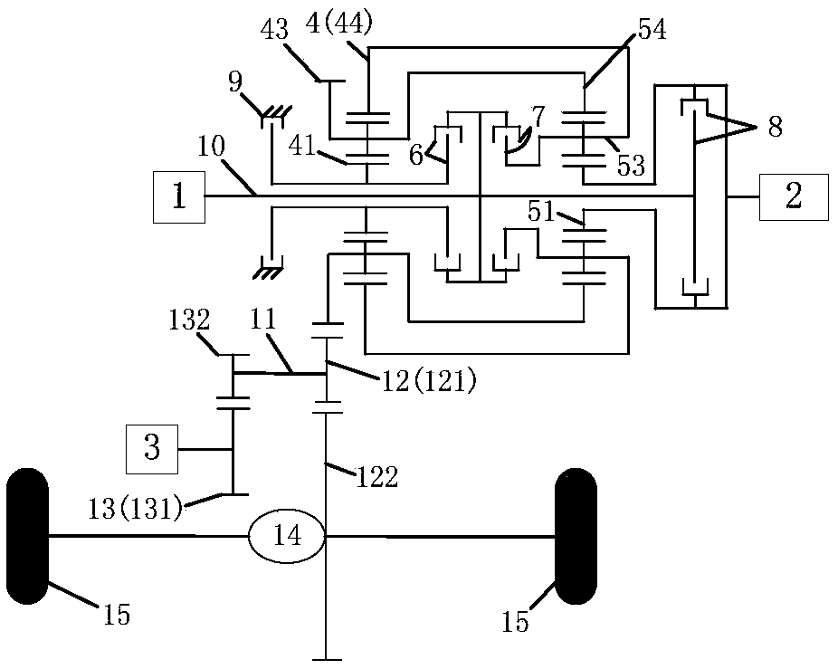
[0133] like Figure 1 to Figure 14 , when the generator 2 is connected to the input shaft 10 through the third clutch 8, and the housing of the third clutch 8 is connected to the rotating shaft of the generator 2 and the second sun gear 51, the hybrid power coupling system has a single motor pure electric mode, a dual Motor pure electric drive mode, hybrid drive mode (with three gears: first hybrid drive mode, second hybrid drive mode, third hybrid drive mode), engine direct drive mode (with three gears: first engine direct drive mode, second Six working modes including two-engine direct-drive mode, third-engine direct-drive mode), ECVT mode (with two gears: first ECVT mode, second ECVT mode) and extended range mode;

[0134] Among them, the aforementioned six working modes are shown in Table 1.

[0135] Table 1

[0136]

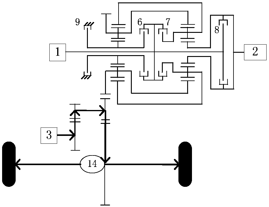
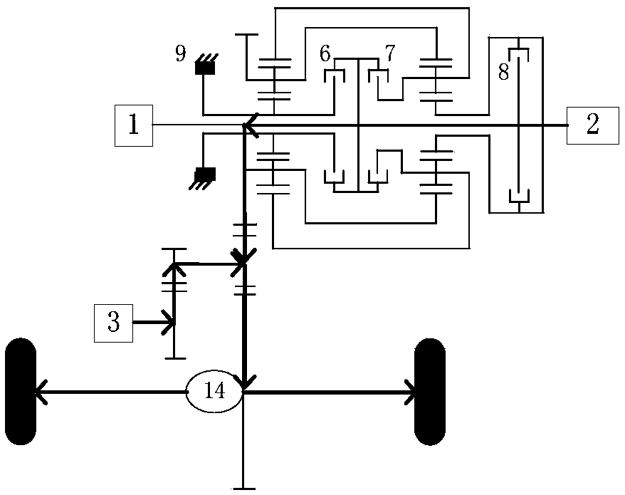
[0137] The following modes, combined with Figure 2 to Figure 14 Describe the power transmission route of the hybrid coupling system, where Figure 5...

Embodiment 2

[0208] When the generator 2 is connected to the second sun gear 51 through the third clutch 8 and is not connected to the input shaft 10, the hybrid power coupling system reduces the first hybrid drive mode and the first engine direct drive mode on the basis of the first embodiment. and range-extending mode, and the third clutch 8 is combined only when the generator 2 is required to participate in driving or power generation, the power of the generator 2 is input into the second sun gear 51 through the third clutch 8, or the power of the second sun gear 51 is input through the third The clutch 8 is input to the generator 2;

[0209] If the third clutch 8 is canceled on the basis of the aforementioned scheme, it is sufficient to cancel the control of the third clutch 8 , and the power lines of each working mode do not need to pass through the third clutch 8 accordingly. To avoid repeating the details, the power routes of each working mode of the scheme will not be listed here; ...

Embodiment 3

[0213] When the generator 2 is connected to the input shaft 10 through the third clutch 8 and is not connected to the second sun gear 51, the hybrid power coupling system reduces the first hybrid drive mode and the first engine direct drive mode on the basis of the first embodiment. 1. In the first ECVT mode and the second ECVT mode, one gear is added to the dual-motor pure electric mode (the two gears are respectively the first dual-motor pure electric mode and the second dual-motor pure electric mode). And the third clutch 8 needs to be combined when the generator 2 participates in driving or generating electricity. The power of the generator 2 is first transmitted to the input shaft 10, and then the CR-CR composite planet is input through the first clutch 6 or the second clutch 7 (embodiment three The power transmission path of the power of the generator 2 from the input shaft 10 to the first planet carrier 43 is consistent with the power transmission path of the power of th...


PUM


Abstract

The invention discloses a hybrid power coupling system and a vehicle. The system comprises an engine, a generator, a driving motor, a first planet row, a second planet row, a brake, a first clutch, asecond clutch, an input shaft and an intermediate shaft for outputting power to wheels, wherein the first planet row comprises a first sun gear, a first planet carrier and a first gear ring, and the second planet row comprises a second sun gear, a second planet carrier connected with the first gear ring and a second gear ring connected with the first planet carrier; the engine is connected with the input shaft; the input shaft is connected with a first sun gear and a second planet carrier through the first clutch and the second clutch respectively; the brake is used for braking the first sun gear, and the first planet carrier is meshed with a first gear arranged on the intermediate shaft; the generator is connected with the second sun gear or the input shaft; and the driving motor is connected with the intermediate shaft. The system load is facilitated to be reduced, multiple driving modes can be achieved, higher transmission efficiency is achieved, and the power performance and economy of the whole vehicle are improved.

Description

technical field [0001] The invention belongs to the field of new energy vehicles, in particular to a hybrid power coupling system and a vehicle. Background technique [0002] The powertrain consists of the engine (internal combustion engine) and a transmission system consisting of a transmission, differential and drive shaft; its function is to provide the vehicle with the driving power required to drive the wheels. Internal combustion engines have a range of speeds and torques, and they work best within a small range where either fuel consumption is minimized, harmful emissions are minimized, or both. However, the actual road conditions are ever-changing, not only in the speed of the driving wheels, but also in the torque required by the driving wheels. Therefore, it is the primary task of the transmission to realize the optimal speed and torque of the internal combustion engine, that is, the optimal state of power, and a good match with the power state of the drive wheel....

Claims


Application Information

Patent Timeline
IPC IPC(8): B60K6/365B60K6/387B60K6/445B60K6/547
CPCB60K6/365B60K6/387B60K6/445B60K6/547Y02T10/62
Inventor 祁宏钟张安伟赵江灵祖国强尚阳任晓华杨洋施国飞
Owner GUANGZHOU AUTOMOBILE GROUP CO LTD
Why Eureka
Try Eureka