Supercooled water dynamic ice storage equipment and ice making method thereof

A technology for supercooled water and ice storage, which can be used in ice making, lighting and heating equipment, and ice manufacturing, etc. It can solve the problems of complex ice making, difficult control of ice storage technology, and easy ice blockage.

Inactive Publication Date: 2020-07-07
广东高精机电设备开发有限公司
View PDF13 Cites 3 Cited by
  • Summary
  • Abstract
  • Description
  • Claims
  • Application Information

AI Technical Summary

Problems solved by technology

[0004] The object of the present invention is to provide a supercooled water dynamic ice storage device that solves the problems of the supercooled water dynamic ice storage technology, which is difficult to control and prone to ice blockage. Ice making method of ice storage equipment with problem of ice blockage

Method used


Image

  • Supercooled water dynamic ice storage equipment and ice making method thereof
  • Supercooled water dynamic ice storage equipment and ice making method thereof
  • Supercooled water dynamic ice storage equipment and ice making method thereof

Examples


Embodiment 1

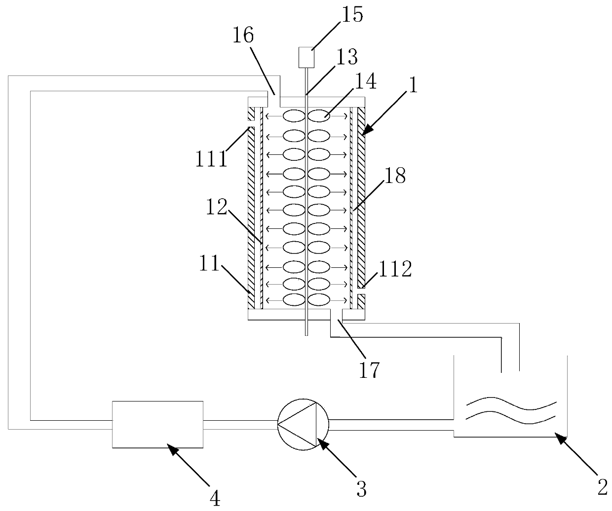
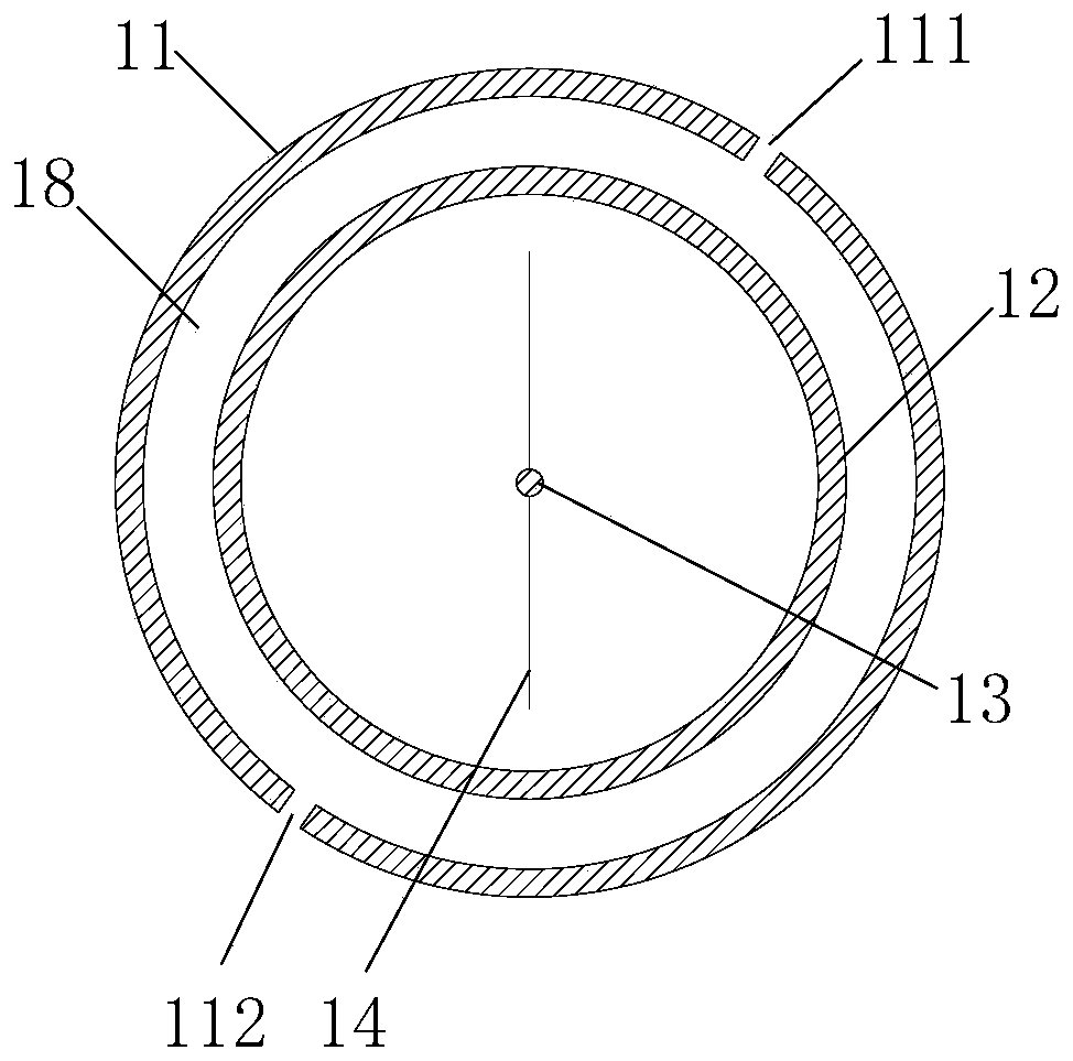
[0030] see figure 1 and image 3 As shown, a kind of supercooled water dynamic ice cold storage equipment includes a cold storage device, an ice storage tank 2, a water pump 3 and a filtering device 4 connected in pairs by pipelines. The cold storage device includes a refrigeration system and a vertical supercooler 1, The supercooler 1 communicates with the outside world through a water inlet 16 and a water outlet 17;

[0031] The supercooler 1 includes an outer cylinder 11, an inner cylinder 12 set inside the outer cylinder, a central transmission shaft 13 that runs through the axis of the outer cylinder 11 and the inner cylinder 12, and a multi-layered and each A layer of blades 14 uniformly distributed around the shaft and a rotating motor 15 connected to the central drive shaft.

[0032] There is a gap between the outer cylinder 11 and the inner cylinder 12 to form a cavity 18. The cylinder body of the outer cylinder is respectively pierced with a refrigerant inlet 111 a...

Embodiment 2

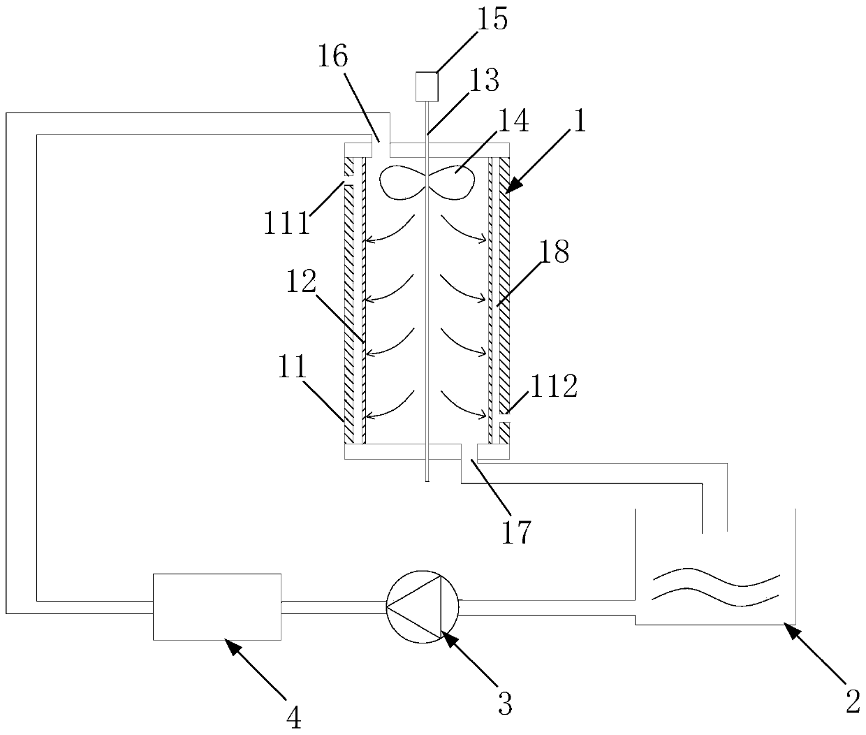
[0038] see figure 2 As mentioned above, the difference between the second embodiment and the first embodiment is that the blades 14 on the central transmission shaft 13 are set, and the end of the central transmission shaft 13 near the water outlet 17 is provided with a single layer of blades 14 evenly distributed around the shaft. .

[0039] The use of this type of blade can drive the water in the inner cylinder to undergo violent radial and axial turbulent movements. From the central transmission shaft to the inner wall of the inner cylinder, the closer to the inner wall of the inner cylinder, the more violent the water flow turbulence.

[0040] An ice making method for supercooled water dynamic ice storage equipment, specifically comprising the following steps:

[0041] (1) Add a certain concentration of solvent to the inner cylinder of the subcooler;

[0042] (2) The refrigeration system is started, and the supply refrigerant enters the cavity from the refrigerant inlet...


PUM


Abstract

The invention relates to supercooled water dynamic ice storage equipment and an ice making method thereof. The supercooled water dynamic ice storage equipment comprises a cold accumulation device, anice storage groove and a water pump, wherein every two of the cold accumulation device, the ice storage groove and the water pump are connected through a pipeline; water circulates in the supercooledwater dynamic ice storage equipment, is cooled into supercooled water in the cold accumulation device, the supercooled water enters the ice storage groove, and water in the ice storage groove enters to the cold accumulation device once more under the action of the water pump to be cooled. The ice making method can realize the dynamic ice making function in a cold accumulation tank; in the cold accumulation tank, ice melts into water, and water enters a subcooler once more to realize circulating ice making, and at the same time, during the process that the subcooler makes supercooled water, aninner cylinder does not generate an ice blockage phenomenon due to icing of the inner cylinder wall.

Description

technical field [0001] The patent of the invention relates to the field of ice storage air conditioners, in particular to a supercooled water dynamic ice storage device and an ice making method thereof. Background technique [0002] Ice storage, as an effective means of cutting peaks and filling valleys, has been greatly developed in recent years. Currently, the mainstream technologies on the market are static ice storage and dynamic ice storage. Supercooled water dynamic ice storage is a kind of dynamic ice storage technology. Its core idea is to let the water cool down to the supercooled state of 0°C in the supercooler without phase change, and eliminate the supercooled state in the cold storage tank. Water at 0°C undergoes a phase transition and becomes ice at 0°C, thereby converting sensible heat into latent heat and storing it to realize dynamic ice production. [0003] However, the supercooled water dynamic ice storage technology is prone to ice blockage in practical...

Claims


Application Information

Patent Timeline
Patent Type & Authority Applications(China)
IPC IPC(8): F24F5/00F25C1/145
CPCF24F5/0017F24F5/0003F25C1/145Y02E60/14
Inventor 王彤徐长锋连培驰
Owner 广东高精机电设备开发有限公司
Why Eureka
Try Eureka