
Power distribution cabinet convenient to maintain

A technology for power distribution cabinets and cabinets, which is applied to the substation/power distribution device shell, electrical components, substation/switch layout details, etc., which can solve problems such as unfavorable inspection and maintenance, failure to meet the use requirements, and intricate lines.

Inactive Publication Date: 2020-07-07
天津华利电力设备有限公司
View PDF0 Cites 1 Cited by
  • Summary
  • Abstract
  • Description
  • Claims
  • Application Information

AI Technical Summary

Problems solved by technology

The installation of components in the power distribution cabinet is relatively complicated. Once a fault occurs inside it, the staff needs to overhaul it repeatedly, and the wiring is intricate. Since the components of the power distribution cabinet are installed inside it, the small space is not conducive to inspection and maintenance, and the lighting is not enough. Ideal, can not meet the needs of use

Method used


Image

  • Power distribution cabinet convenient to maintain
  • Power distribution cabinet convenient to maintain
  • Power distribution cabinet convenient to maintain

Examples


Embodiment 1

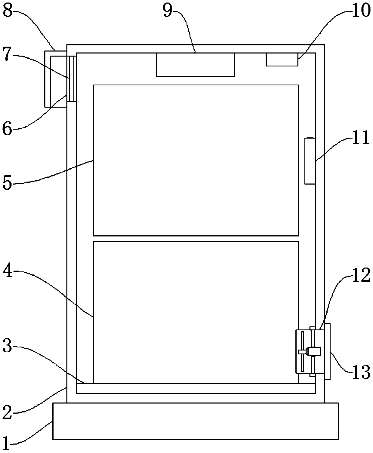
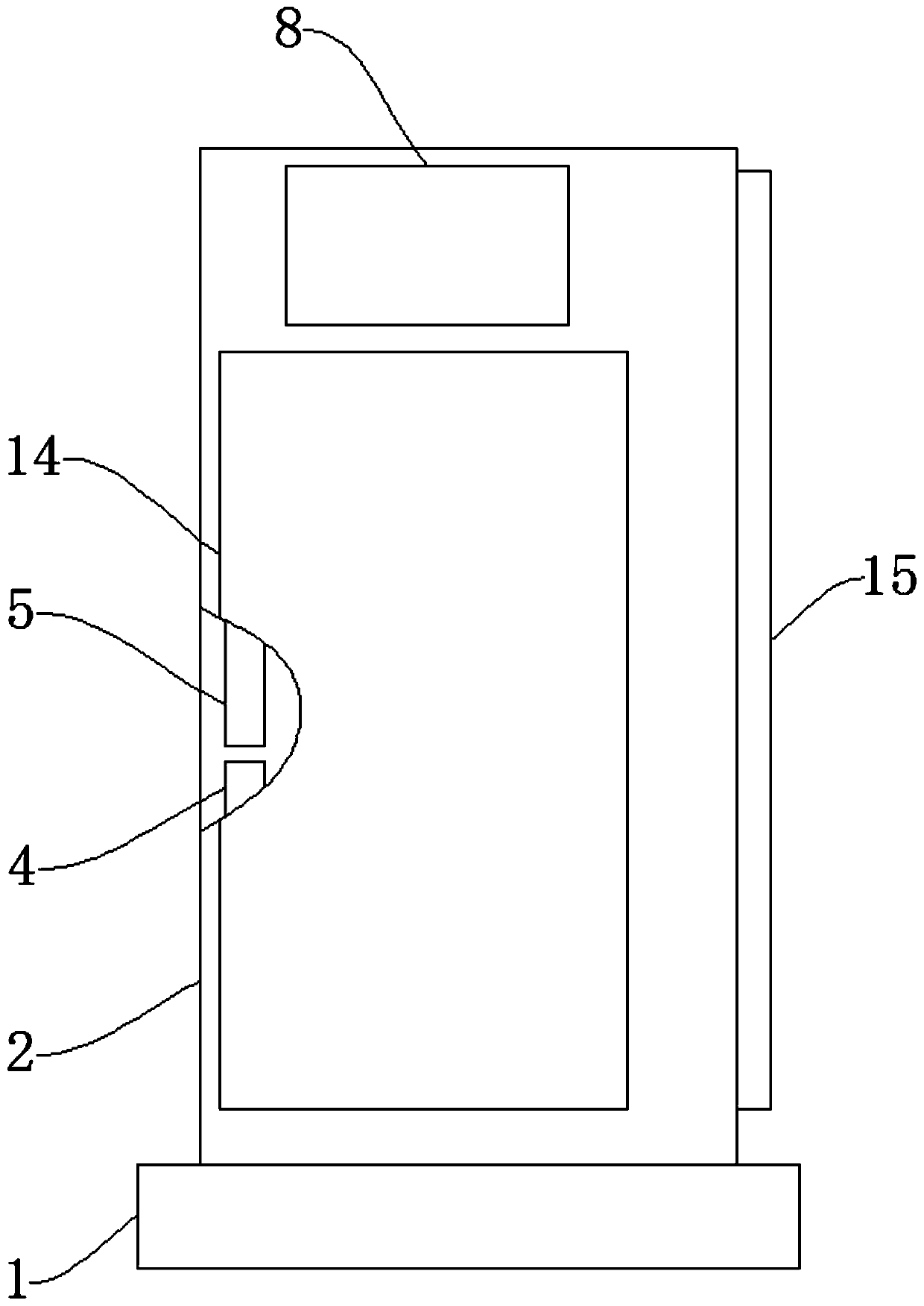
[0026] Such as Figure 1-Figure 3 As shown, a power distribution cabinet that is easy to maintain includes a waterproof platform 1, a lower mounting plate 4, a lighting lamp 9 and a controller 11. A cabinet body 2 is arranged on the upper end of the waterproof platform 1, and a moisture-proof board 3 is installed inside the cabinet body 2. The moisture-proof plate 3 is used for moisture-proof, the lower mounting plate 4 is installed above the moisture-proof plate 3, the upper mounting plate 5 is installed above the lower mounting plate 4, and the side wall of the cabinet body 2 is provided with a vent 6, and the vent hole 6 is used for the cabinet body 2 For internal ventilation, a dust-proof grid 7 is installed inside the vent 6, a rain cover 8 is installed outside the vent 6, a lighting lamp 9 is installed inside the cabinet body 2, and a battery 10 is installed on one side of the lighting lamp 9, and the battery 10 is used for lighting. The lamp 9 is powered, the inner wall...

Embodiment 2

[0028] The difference between this embodiment and Embodiment 1 is that in this embodiment, the moisture-proof board 3 is fixed on the bottom of the cabinet body 2 by glue.

[0029] Specifically, such setting can make the connection of the device more stable, and can also make the moisture-proof board 3 easy to disassemble and replace.

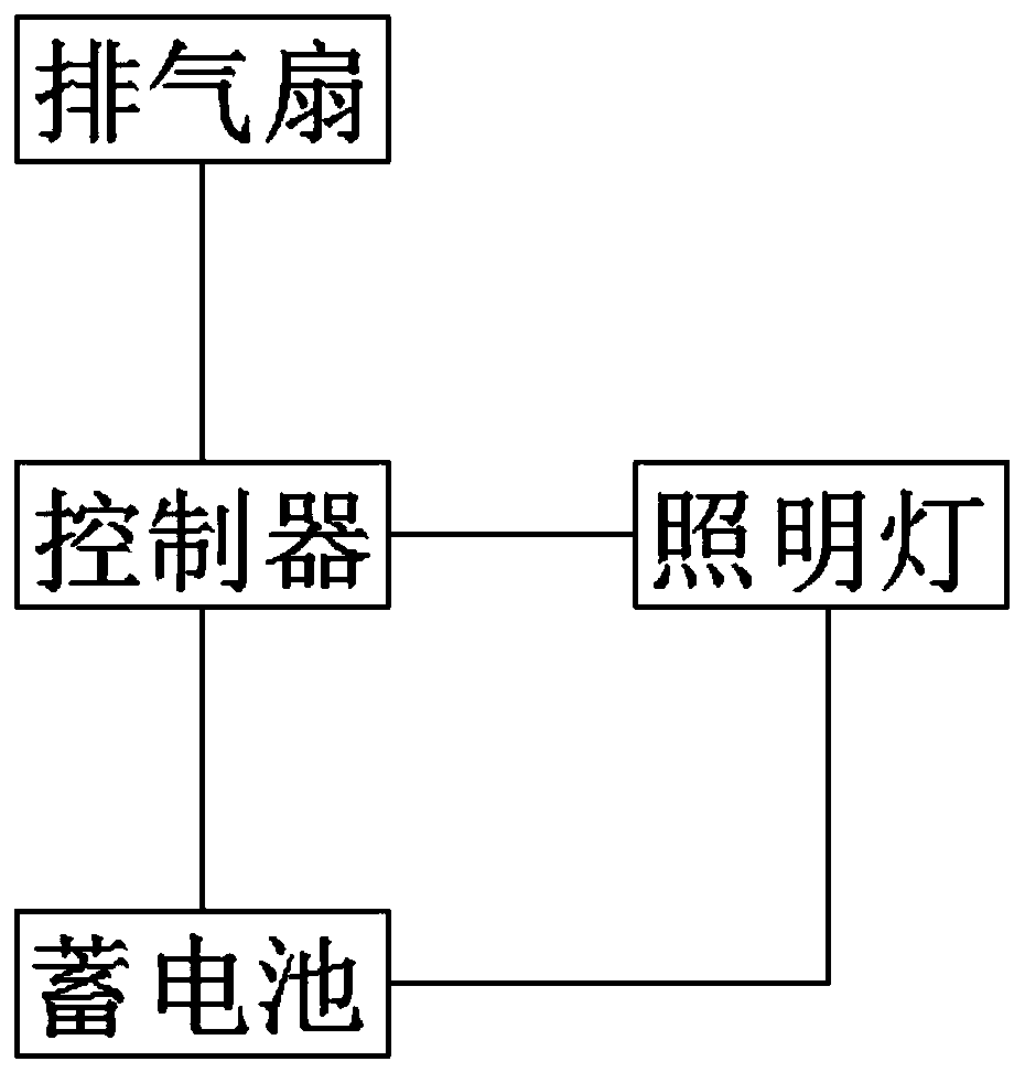
[0030] The specific working principle of the present invention is: the electrical components are respectively installed on the upper mounting plate 5 and the lower mounting plate 4, when the electrical components in the device work and generate heat, the exhaust fan 12 can be controlled by the controller 11 to work, and the exhaust fan 12 The air inside the cabinet 2 is discharged, while the outside air is filtered by the dust-proof grid 7 and enters the cabinet 2. The rain cover 8 prevents rainwater from entering the cabinet 2 through the dust-proof grid 7. When the device needs to be overhauled , the cabinet door 15 can be opened, the electri...


PUM


Abstract

The invention discloses a power distribution cabinet convenient to maintain. The power distribution cabinet comprises a waterproof table, a lower mounting plate, an illuminating lamp and a controller;wherein a cabinet body is arranged at the upper end of the waterproof table and a moisture-proof plate is installed in the cabinet body. An upper mounting plate is mounted above the lower mounting plate; a ventilation opening is formed in the side wall of the cabinet body; a dustproof grid is installed in the ventilation opening, a rainproof cover is arranged on the outer side of the ventilationopening, the illuminating lamp is installed in the cabinet body, an exhaust fan is arranged below the controller, a filtering cover is arranged on the outer side of the exhaust fan, a side door is arranged on the side face of the cabinet body, and a cabinet door is arranged on one side of the cabinet body. The power distribution cabinet has the beneficial effects: by arranging the side door, the power distribution cabinet is convenient to check and maintain and high in practicability; 2, the upper mounting plate and the lower mounting plate are arranged, so that electric devices are separatelymounted and are convenient to maintain; 3, power can be independently supplied to the illuminating lamp, so that the power distribution cabinet is more convenient to illuminate; and 4, the power distribution cabinet is convenient to ventilate, dustproof and moistureproof, and the safety is improved.

Description

technical field [0001] The invention relates to the technical field of power distribution cabinets, in particular to a power distribution cabinet that is easy to maintain. Background technique [0002] Power distribution cabinets are divided into power distribution cabinets, lighting distribution cabinets, and metering cabinets. They are the final equipment of the power distribution system. The electrical energy of a certain circuit of the first-level power distribution equipment is distributed to the nearest load. The installation of components in the power distribution cabinet is relatively complicated. Once a fault occurs inside it, the staff needs to overhaul it repeatedly, and the wiring is intricate. Since the components of the power distribution cabinet are installed inside it, the small space is not conducive to inspection and maintenance, and the lighting is not enough. Ideal, but cannot meet the needs of use. Contents of the invention [0003] The object of the...

Claims


Application Information

Patent Timeline
IPC IPC(8): H02B1/30H02B1/28H02B1/56
CPCH02B1/28H02B1/30H02B1/565
Inventor 李金竹万福钰范金武马德堃
Owner 天津华利电力设备有限公司
Learn More