A strip position detection device for water cooling section

A detection device and segment technology, which is applied to length measuring devices, metal processing equipment, metal rolling, etc., can solve problems such as the inability of electrical position sensors to obtain accurate electrical signals, poor electrical position sensors, and safety production accidents. Accurate calibration signal, reliable effect, accurate cooling strategy effect

Active Publication Date: 2011-11-30
BAOSHAN IRON & STEEL CO LTD
View PDF4 Cites 7 Cited by
  • Summary
  • Abstract
  • Description
  • Claims
  • Application Information

AI Technical Summary

Problems solved by technology

[0011] The electric position sensor is not suitable for the use of the water-cooling section. The reason is that the roller table, nozzle, steel plate and other devices in the water-cooling section are all metal parts, and the electric position sensor cannot obtain accurate electrical signals. Therefore, the effect of directly using the electric position sensor is relatively low. Difference
[0012] To sum up, the detection methods in the existing technology are either because of their high cost or because they cannot adapt to the working conditions of the water-cooled section, which makes it difficult to detect the position of the strip when it passes through the water-cooled section of the hot-rolled steel production line. , which directly affects the follow-up production work. In severe cases, detection errors will cause plates and strips to collide with each other, causing safety production accidents

Method used


Image

  • A strip position detection device for water cooling section
  • A strip position detection device for water cooling section
  • A strip position detection device for water cooling section

Examples


Embodiment

[0035] Such as figure 1 and figure 2 As shown, a strip position detection device for a water-cooling section of the present invention, the installation steps are as follows:

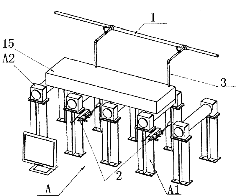
[0036] 1. First, determine the specific quantity of the strip position detection device for the water-cooling section of the present invention that needs to be installed according to the length of the water-cooling section frame group A, and the number is 2 in this embodiment;

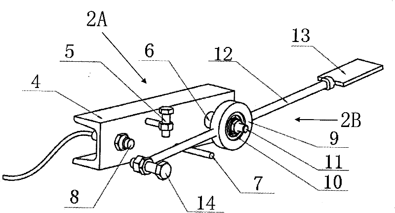
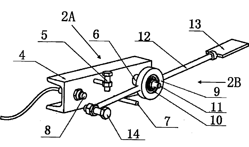
[0037] 2. Weld and install the strip position detection device for the water-cooling section of the present invention on the roller table support A1 below the roller table A2, without affecting the position of the existing lower water spray nozzle; The water plate 13 is facing the nozzle of each water spray pipe 3 of the spray water pipe group 1 above.

[0038] It is ready to use after installation.

[0039] Such as figure 1 and figure 2 As shown, a strip position detection device for a water-cooling section of the present...


PUM


Abstract

The invention discloses a slab band position detecting device for a water cooling zone. A roller bed bracket below a roller bed of a water cooling zone frame group is provided with the slab band position detecting device consisting of a fixedly-mounted component and a rotational component; the rotational component is connected with the fixedly-mounted component; specifically, a bearing outer sleeve is sleeved on a connecting rod of the rotational component and is fixed by using a bearing and a fixing bolt so that the bearing outer sleeve can rotate at the connecting rod; the left end and right end of the bearing outer sleeve are respectively connected and provided with the connecting rod; the connecting rods at the two ends are in a lever shape; the connecting rod at the right end is provided with a water bearing plate; the surface of the water bearing plate is aligned with a position below a water spraying pipe; the connecting rod at the left end is arranged between an upper connecting rod detent and a lower connecting rod detent, and the end of the connecting rod is further provided with an induction bolt; the upper-limit movement locus of the induction bolt is coincident with aproximity switch and is limited by the upper connecting rod detent; and the lower-limit movement locus of the induction bolt is limited by the lower connecting rod detent. The device provided by the invention is applicable to the position detection field of the auxiliary calibration of a slab band position in a hot rolling and water cooling zone.

Description

technical field [0001] The invention relates to the field of detection devices, in particular to a device for detecting the position of a hot-rolled steel plate / strip passing through a water-cooled section of a hot-rolled iron and steel production line. Background technique [0002] At present, various iron and steel production enterprises have widely used complete sets of hot steel hot rolling production line equipment in their hot steel rolling production. Among them, one of the key parts of the hot rolling production line - the water cooling section, whether the section is working normally or not It directly affects whether the production of the whole hot rolling production line goes on smoothly. [0003] The key to the normal operation of the water-cooled section is that when the hot-rolled steel sheet / strip (abbreviated as the strip) runs in this position section, whether its position detection mechanism can operate normally, while the hot-rolled line water cooling in t...

Claims


Application Information

Patent Timeline
Patent Type & Authority Applications(China)
IPC IPC(8): B21B38/00
Inventor 朱健桦王笑波
Owner BAOSHAN IRON & STEEL CO LTD
Why Eureka
Try Eureka