Hand-push-type positioned seeding device for peanut planting

A peanut planting and seeding device technology, applied in the directions of sowing, fertilizing devices, planter parts, etc., can solve the problems of misaligned ground ridges, peanut seed damage, stuck peanut seeds, etc., and achieve the effect of accurate positioning

Active Publication Date: 2020-07-10
天辰兰德(山东)科技服务有限公司
View PDF10 Cites 2 Cited by
  • Summary
  • Abstract
  • Description
  • Claims
  • Application Information

AI Technical Summary

Problems solved by technology

[0007] In order to overcome the problem of the hand-push single-wheel planter, the hand-push single-wheel seeder not only often runs off the ridge, but also overturns if it is not supported properly, so that the peanut seeds are scattered all over the ground. Peanut seeds are often stuck, which not only damages the peanut seeds, but also sometimes leads to the lack of sowing in place and a long piece o...

Method used


Image

  • Hand-push-type positioned seeding device for peanut planting
  • Hand-push-type positioned seeding device for peanut planting
  • Hand-push-type positioned seeding device for peanut planting

Examples


Embodiment 1

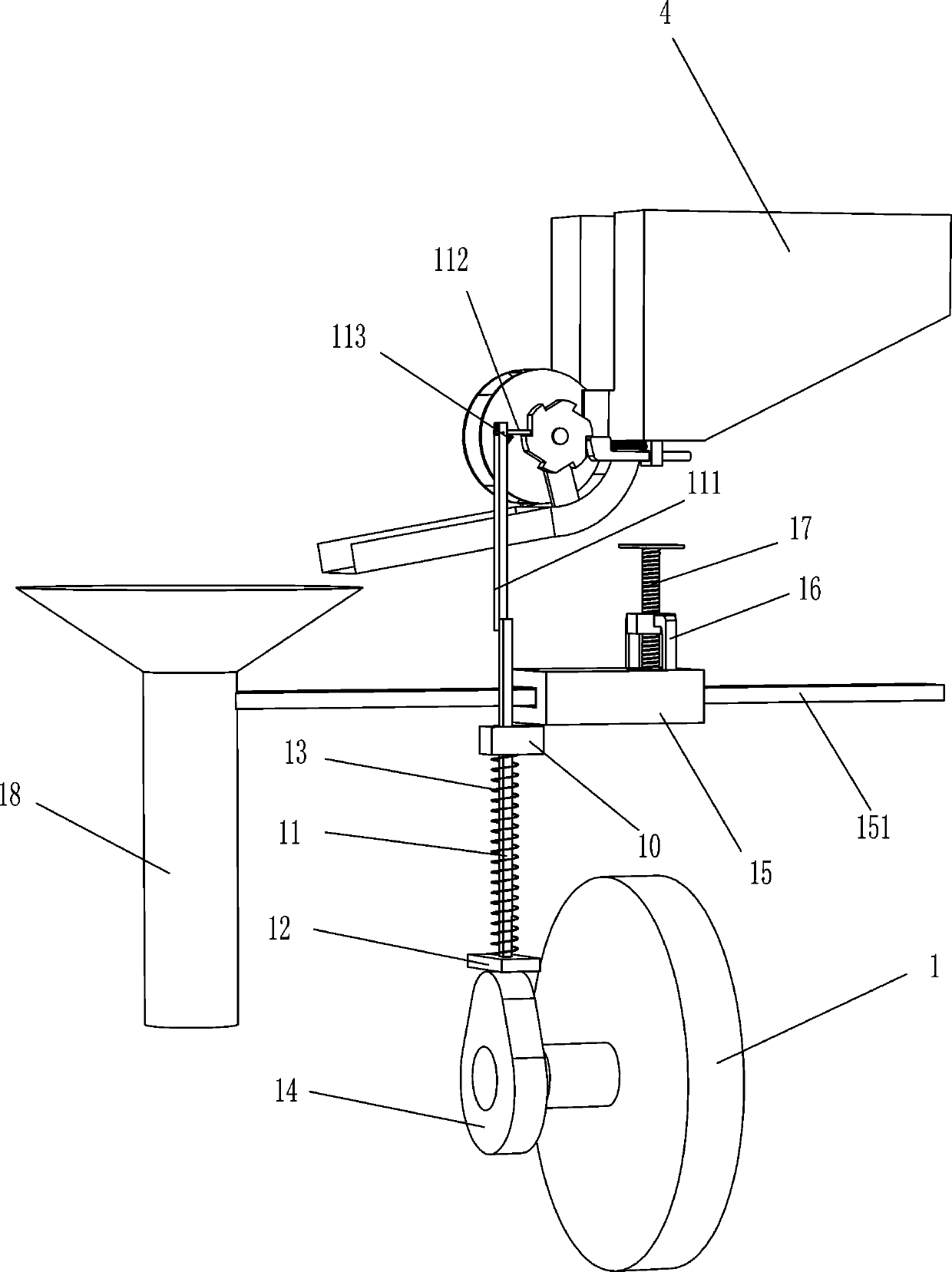
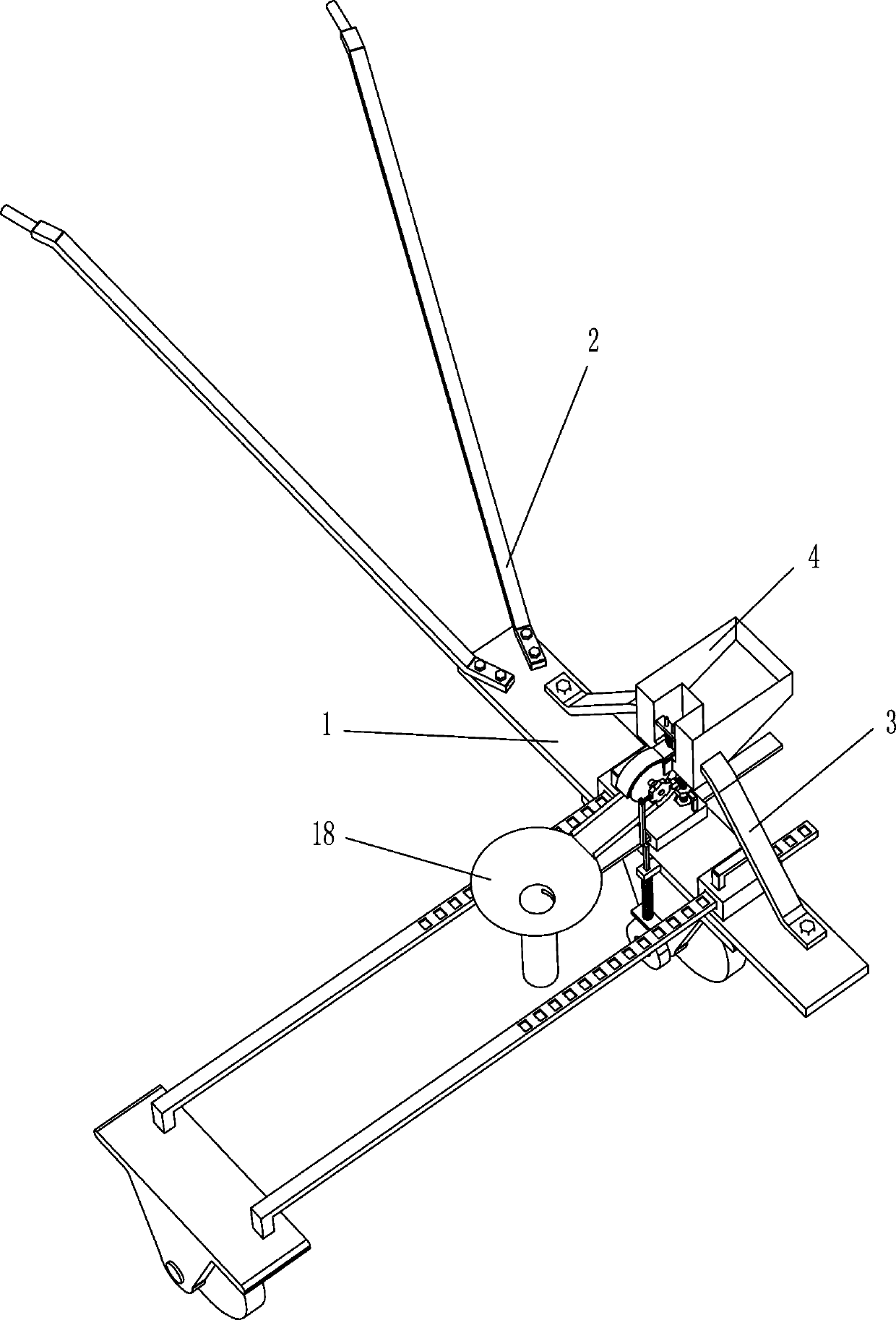
[0059] A hand-push peanut planting positioning sowing device, as shown in the figure, such as Figure 1-3 As shown, it includes vehicle frame 1, handrail 2, supporting plate 3, charging box 4, drain plate 5, rotating shaft 6, feeding tray 7, chuck 8, clamping device 9, movable sliding sleeve 10, sliding rod 11, pole 111, swing bar 112, top spring 113, top plate 12, return spring 13, cam 14, guide sleeve 15, guide rod 151, nut 16, screw rod 17 and funnel 18, vehicle frame 1 is equipped with wheels, Two handrails 2 are fixedly connected to the upper left side of the vehicle frame 1, and the two handrails 2 are symmetrical. The lower ends of the two support plates 3 are fixedly connected to the left and right sides above the vehicle frame 1. The upper end of the support plate 3 is fixedly connected and is located in the middle of the two support plates 3. The charging box 4 is provided with a leakage hole. The leakage plate 5 is connected to the bottom of the charging box 4. The ...

Embodiment 2

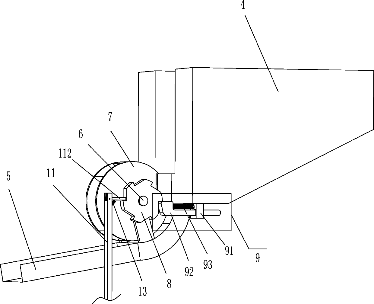
[0062] On the basis of Example 1, such as image 3 As shown, the clamping device 9 includes a clamping sliding sleeve 91, a clamping lever 92 and a return spring 93, the clamping sliding sleeve 91 is fixedly connected to the lower right side of the charging box 4, and the clamping lever 92 is slidably connected to the Inside the tight sliding sleeve 91 , the clamping rod 92 is in contact with the chuck 8 , one end of the return spring 93 is fixedly connected to the clamping sliding sleeve 91 , and the other end is fixedly connected to the clamping rod 92 .

[0063] When the chuck 8 rotated one tooth forward, the clamping rod 92 clamped the chuck 8 under the promotion of the back-moving spring 93 to prevent the reverse rotation of the chuck 8, and the clamping rod 92 cooperated with the swing rod 112.

[0064] Such as Figure 4 As shown, it also includes an adjustment sleeve 19, an adjustment rod 20, a draw-in groove 21, a fixed clamp rod 22 and a balance wheel 23. There are ...

Embodiment 3

[0067] On the basis of Example 2, such as Figure 5 As shown, it also includes a fixed plate 24, a cylindrical rod 25, a hold-down plate 26 and a hold-down spring 27. The fixed plate 24 is affixed to the middle part of the front side outer wall of the charging box 4, and the fixed plate 24 has two through holes. Two cylindrical rods 25 pass through the through holes on the fixing plate 24 respectively, the two cylindrical rods 25 are symmetrical, and the pressing plate 26 is fixedly connected to the lower ends of the two cylindrical rods 25, and the pressing plate 26 is located at the bottom of the charging box 4 leakage hole and Above the material tray 7, one end of the compression spring 27 is affixed to the bottom of the fixed plate 24, and the other end is affixed to the top of the compression plate 26. The compression spring 27 is located in the middle of the two cylindrical rods 25.

[0068] When too many peanut seeds are piled up from the leakage hole, the pressing plat...


PUM


Abstract

The invention relates to a peanut planting device, in particular to a hand-push-type positioned seeding device for peanut planting. The technical problem to be solved is to provide the hand-push-typepositioned seeding device, for peanut planting, which can keep balance and is not liable to roll over during seeding when pushed, and is not liable to deviate from ridges during seeding due to the fact that the distance between two wheels can be flexibly adjusted. The hand-push-type positioned seeding device for peanut planting comprises a frame, armrests, supporting boards and a container, wherein the wheels are installed below the frame; the two armrests are fixedly connected with the frame, and the two armrests are symmetric; the lower ends of the two supporting boards are fixedly connectedwith the frame, and the two supporting boards are symmetric; and the container is fixedly connected with the upper ends of the two supporting boards, and is located between the two supporting boards,and a leak is formed in the container. The hand-push-type positioned seeding device for peanut planting is more energy-saving when pushed manually, and can keep balance and is not liable to roll overwhen pushed, and the distance between the two wheels can be flexibly adjusted, so that the hand-push-type positioned seeding device for peanut planting is not liable to deviate from the ridges duringseeding.

Description

technical field [0001] The invention relates to a peanut planting device, in particular to a hand-push peanut planting positioning and sowing device. Background technique [0002] Peanut is also known as groundnut, dicotyledonous plant, the veins of the leaves are reticular veins, and the seeds are covered with peanut peel. In history, it was called longevity fruit, ground bean, falling flower ginseng, falling pine, Chengshou fruit, fandou, fig, ground fruit, and Tang Rendou. Flowers grow in nourishment and nourishment, and help to prolong life, so the folks are also called "longevity fruit", and like soybeans, they are known as "vegetable meat" and "vegetable meat". [0003] In recent years, with the enhancement of people's awareness of environmental protection, safety and health, people are afraid that the peanut oil they buy will be counterfeit and unauthentic. People want to eat peanuts grown by themselves, especially farmers in North China, who grow small-scale peanuts...

Claims


Application Information

Patent Timeline
IPC IPC(8): A01C7/00A01C7/08A01C7/20A01C19/04
CPCA01C7/002A01C7/085A01C7/20A01C19/04Y02P60/21
Inventor 成家振
Owner 天辰兰德(山东)科技服务有限公司
Why Eureka
Try Eureka