Positioning structure of carpentry machining center

A positioning structure, processing center technology, applied in wood processing appliances, manufacturing tools, special forming/shaping machines, etc., can solve problems such as poor positioning stability, and achieve high positioning stability, flexible use, and improved positioning stability. Effect

Active Publication Date: 2020-07-10
吴善旺
View PDF9 Cites 6 Cited by
  • Summary
  • Abstract
  • Description
  • Claims
  • Application Information

AI Technical Summary

Problems solved by technology

[0004] The purpose of the present invention is to solve the above-mentioned problems in the existing technology, and propose a positioning structure for woodworking processing centers to solve the problem of poor positioning stability of the existing woodworking processing centers for workpieces with irregular shapes

Method used


Image

  • Positioning structure of carpentry machining center
  • Positioning structure of carpentry machining center
  • Positioning structure of carpentry machining center

Examples


Embodiment 1

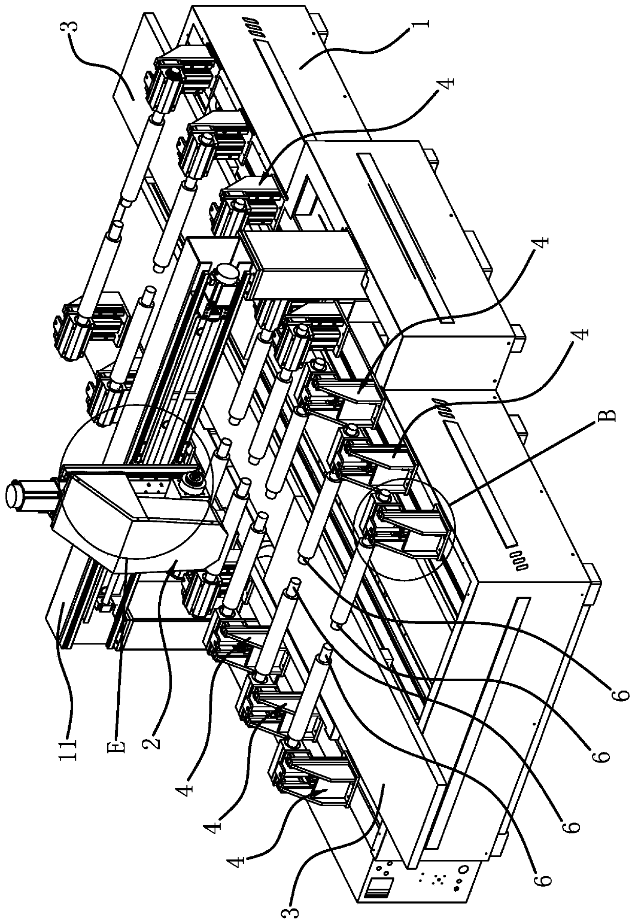
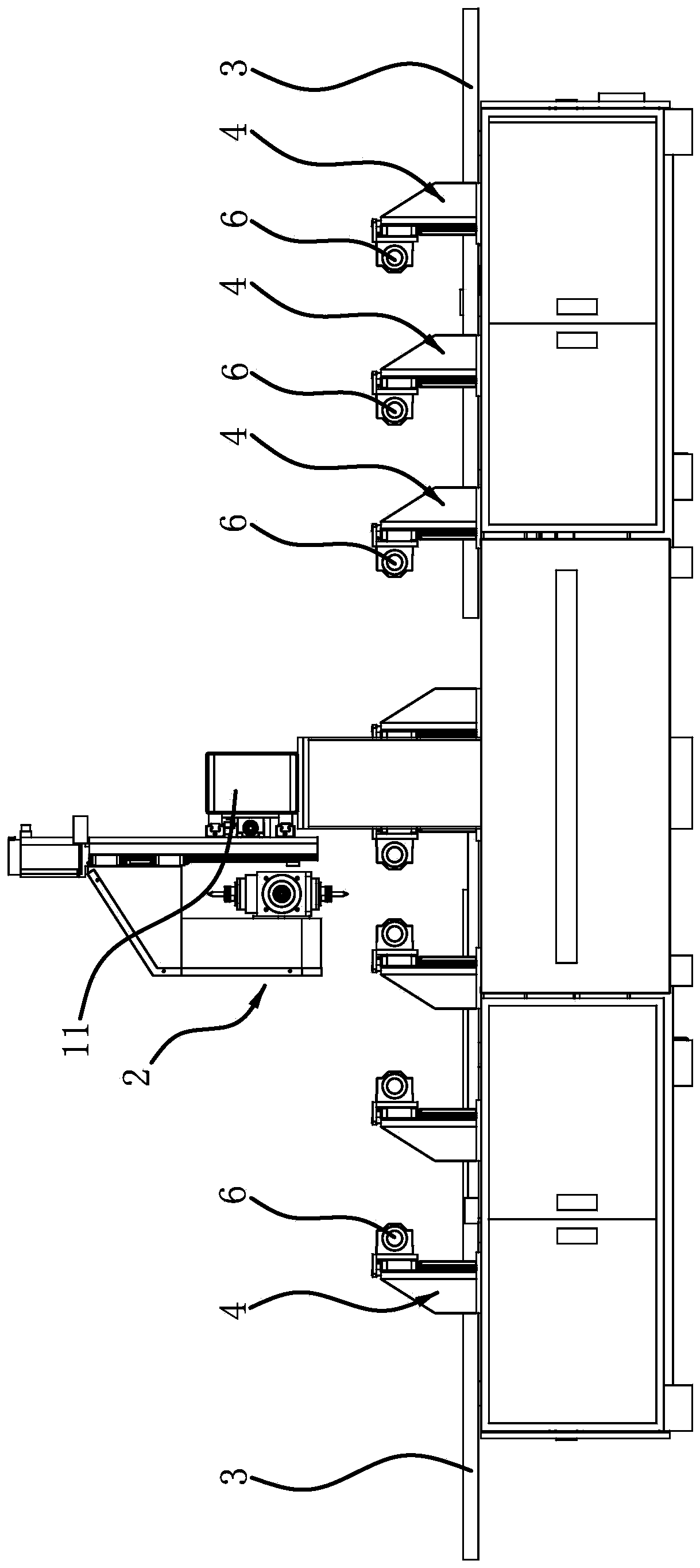
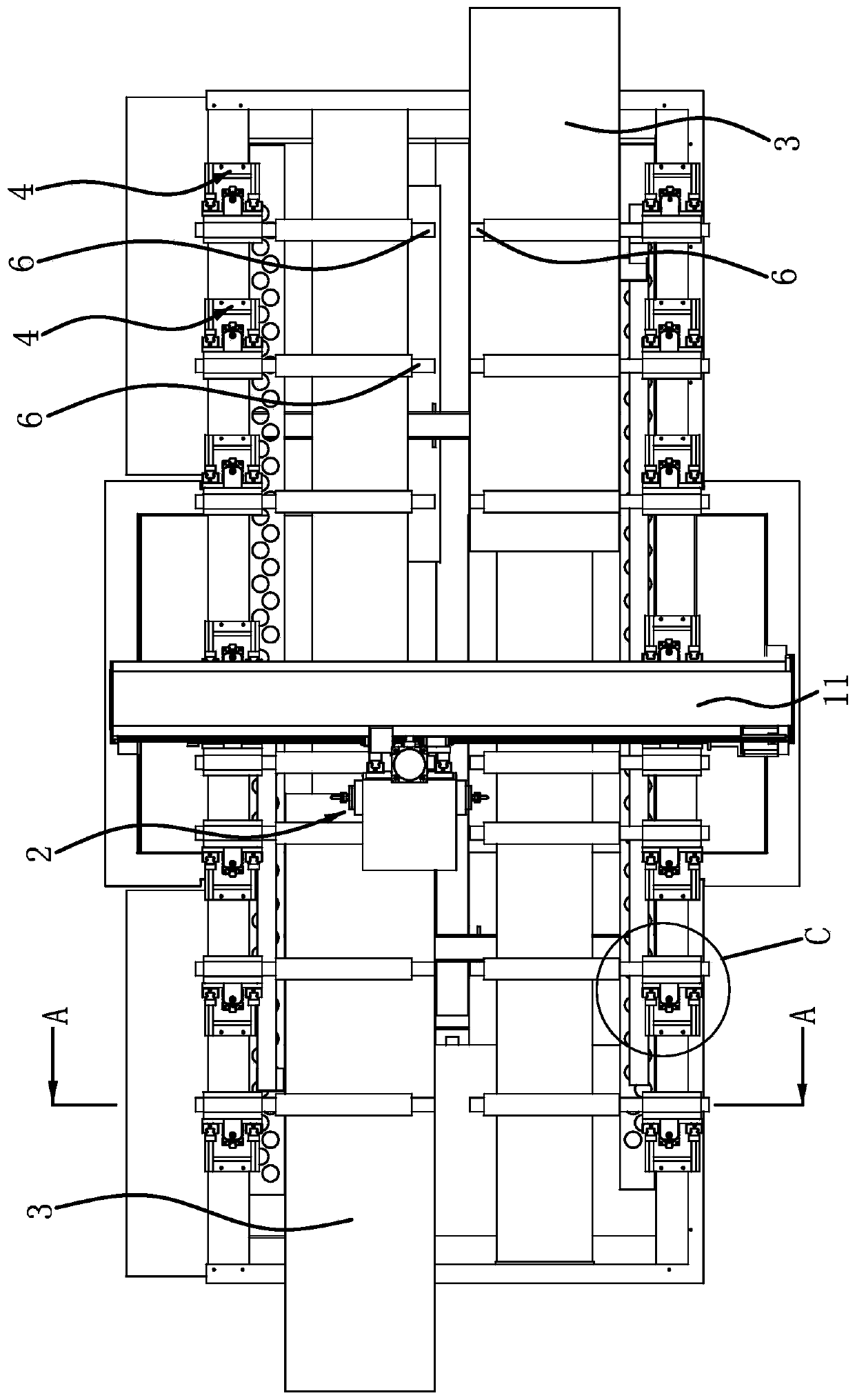
[0034] Such as Figure 1 to Figure 4 As shown, the positioning structure of the woodworking processing center, the woodworking processing center includes a frame 1 and a crossbeam 11, vertical columns are fixed on both sides of the longitudinal middle of the frame 1, the crossbeam 11 is arranged horizontally, and the two ends of the crossbeam 11 are respectively fixed At the top of the two columns, on one side of the beam 11, the processing assembly 2 is connected with the horizontal carriage 8 and the vertical carriage 9, and the movement of the horizontal carriage 8 and the vertical carriage 9 realizes the horizontal movement and the vertical movement of the processing assembly 2 , and on the frame 1, there are two processing platforms 3 longitudinally slidably connected. The two processing platforms 3 are strip-shaped and arranged longitudinally for placing workpieces. Therefore, three-dimensional translation can be realized between the processing assembly 2 and the process...

Embodiment 2

[0038] The positioning structure of this woodworking processing center is basically the same as that of Embodiment 1, the difference is that Figure 9 , Figure 10 As shown, an adjusting plate 55 is fixed on the lifting seat 5, and the adjusting plate 55 is connected to the lifting plate 52 by rotating the rotating disk 56, so that the positioning pressure roller 6 can swing in the vertical plane, and the adjusting plate 52 is vertically fixed on the lifting plate 52 Cylinder 57, the piston rod of the adjustment cylinder 57 is vertically downward, and one side edge of the adjustment plate 55 has a protruding adjustment part 551, the adjustment part 551 is in the shape of a strip plate, and the adjustment part 551 is arc-shaped along the length direction And arched upwards, the adjustment part 551 is provided with a strip hole 552 along the length direction, and the piston rod end of the adjustment cylinder 57 has a stepped surface 571 in the circumferential direction, and the ...


PUM


Abstract

The invention provides a positioning structure of a carpentry machining center and belongs to the technical field of machining equipment. The problem that the positioning stability of irregular-shapedworkpieces by an existing carpentry machining center is poor is solved. The carpentry machining center of the positioning structure comprises a machine frame and a transverse beam which is fixed to the machine frame; a machining assembly is disposed on the transverse beam; and a machining platform is slideably disposed on the machine frame in the horizontal direction. The positioning structure comprises a plurality of installing seats which are arranged on the machine frame; positioning pressure rollers are horizontally disposed on the installing seats correspondingly; the plurality of installing seats are arranged in two rows; lifting seats are slideably connected to the installing seats in the vertical direction correspondingly; one ends of the positioning pressure rollers are connectedto the lifting seats, and the other ends of the two rows of positioning pressure rollers face the inner side of the machine frame; when the lifting seats ascend, the other ends of the two rows of positioning pressure rollers can be located above the machining platform; and each installing seat is provided with a driving part. The positioning stability of the irregular-shaped workpieces by the carpentry machining center is higher.

Description

technical field [0001] The invention belongs to the technical field of mechanical processing equipment, and relates to a positioning structure of a woodworking processing center. Background technique [0002] Woodworking processing center, such as engraving and milling machine is a kind of processing equipment that can engrave and mill the workpiece. The engraving and milling machine is equipped with a motor that can move in multiple dimensions. The output shaft of the motor is equipped with a tool to perform three-dimensional processing on the workpiece. , and the workpiece needs to be positioned on the processing platform, so a positioning structure for locating the workpiece will be provided on the processing platform, such as the saw blade machine disclosed in the patent document (application number: 201320302954.9), including the wheel set on the frame Saw group, plank moving guiding device, motor, platen device, and dust removal device; the platen device is provided wi...

Claims


Application Information

Patent Timeline
Patent Type & Authority Applications(China)
IPC IPC(8): B27C9/02B27C5/02B27C5/06
CPCB27C9/02B27C5/02B27C5/06
Inventor 吴善旺
Owner 吴善旺
Why Eureka
Try Eureka