Distributed locomotive electronic brake control system

An electronic braking and control system technology, applied in the direction of braking safety systems, brakes, brake components, etc., can solve the problems of high failure rate and high integration, and achieve the effect of improving reliability, reducing complexity and facilitating maintenance

Inactive Publication Date: 2020-07-10
CRRC QINGDAO SIFANG ROLLING STOCK RES INST +1
View PDF4 Cites 0 Cited by
  • Summary
  • Abstract
  • Description
  • Claims
  • Application Information

AI Technical Summary

Problems solved by technology

[0005] In order to solve the technical problems of excessive integration and high failure rate in the electronic braking control system in the prior art, the present invention provides a distributed electronic braking control system for locomotives, which adopts a distributed architecture and uses independent

Method used


Image

  • Distributed locomotive electronic brake control system
  • Distributed locomotive electronic brake control system
  • Distributed locomotive electronic brake control system

Examples


Embodiment 1

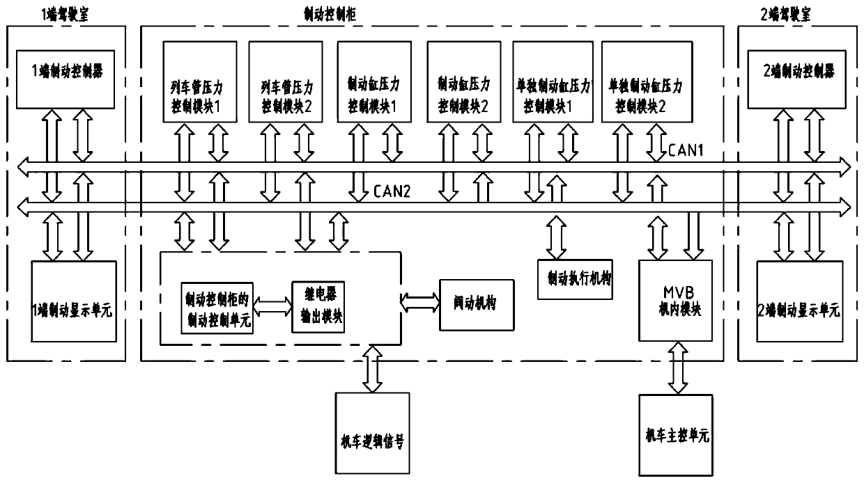
[0042] Specifically, refer to the attached figure 1 , figure 1 It is a schematic structural diagram of a distributed 6-axle locomotive electronic brake control system provided by the embodiment of the present invention, including a communication unit, a brake controller, a locomotive main control unit, a brake control cabinet, and a brake display unit. The brake controller, the locomotive main control unit, the brake control cabinet and the brake display unit are communicatively connected through the communication unit. The brake control unit controls the valve mechanism according to the control information of the brake controller, the locomotive main control unit and the brake display unit; Information and data information of the brake actuator to control the brake actuator. The control information includes: brake handle control information sent by the brake controller, locomotive-level brake command control information sent by the locomotive main control unit, and locomoti...

Embodiment 2

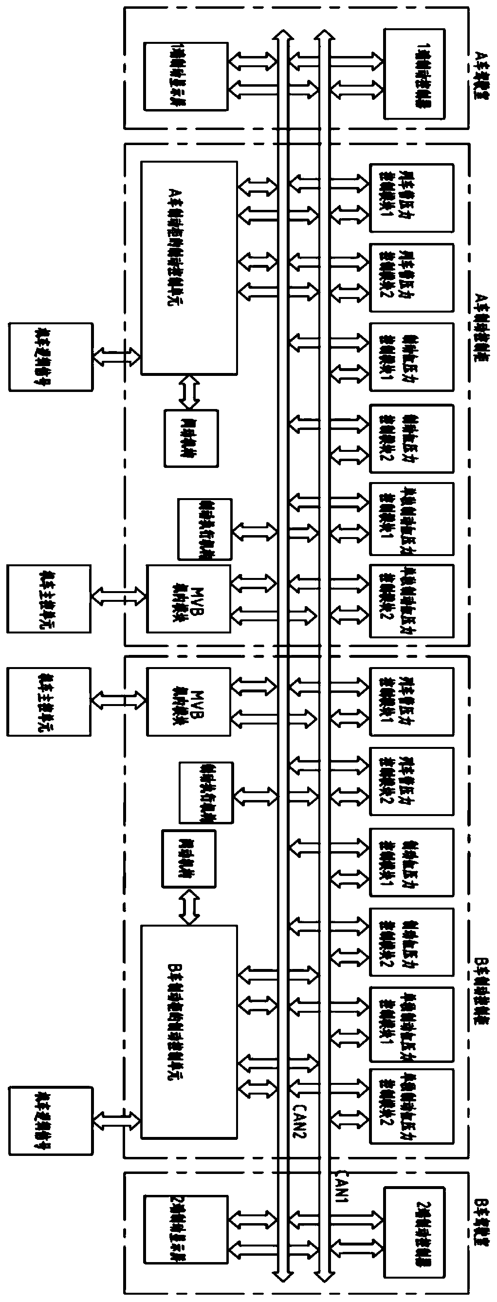
[0056] Specifically, refer to the attached image 3 , image 3 It is a schematic structural diagram of a distributed 8-axle locomotive electronic brake control system provided by the embodiment of the present invention. The 8-axle locomotive electronic brake control system includes: a communication unit, a brake controller, a locomotive main control unit, and a brake control cabinet And the brake display unit, wherein the structure and composition of the communication unit, brake controller, locomotive main control unit, brake control cabinet and brake display unit are consistent with the electronic control system of the 6-axle locomotive, and the electronic brake of the 6-axle locomotive The difference in the control system is that the 8-axle locomotive is composed of two 4-axle locomotives articulated, and the electronic brake control system of the 8-axle locomotive includes: two brake control cabinets and two locomotive main control units. One brake control cabinet and the...


PUM


Abstract

The invention provides a distributed locomotive electronic brake control system comprising a communication unit, a brake controller, a locomotive main control unit, a brake control cabinet and a brakedisplay unit, wherein the brake controller, the locomotive main control unit, the brake control cabinet and the brake display unit are connected through the communication unit. The brake control cabinet comprises a brake control unit, an electric air control unit, a valve driving mechanism and a brake executing mechanism; the brake control unit controls the valve driving mechanism according to control information of the brake controller, the locomotive main control unit and the brake display unit; and the electric air control unit controls the brake executing mechanism according to the control information of the brake controller, the locomotive main control unit and the brake display unit and data information of the brake executing mechanism. According to the invention, the integration level of the electronic brake control system and the range of fault influence are reduced, the complexity of the system is reduced, the maintenance is convenient, and the reliability of the electronic control system is improved.

Description

technical field [0001] The invention relates to the technical field of locomotive brake control, in particular to a distributed electronic brake control system for locomotives. Background technique [0002] The electronic brake control system is the core of the locomotive brake system. Its main function is to receive the brake commands issued by the driver's brake controller and the locomotive main control system, collect the signals of the balanced air cylinder pressure sensor, the signal of the train pipe pressure sensor, and the independent braking system. Dynamic pressure sensor signal and total wind pressure sensor signal, etc., and collect the logic signal sent by the locomotive main control unit, through mathematical calculation and logic operation, control the train pipe pressure, locomotive brake cylinder pressure and individual brake pressure, and realize automatic braking , independent braking, emergency braking, penalty braking and braking reconnection and other ...

Claims


Application Information

Patent Timeline
IPC IPC(8): B60T17/22B60T13/68
CPCB60T13/683B60T17/228
Inventor 王其伟王令军王超逸许丰磊刘澳李莉杨乐曾祥辉
Owner CRRC QINGDAO SIFANG ROLLING STOCK RES INST
Why Eureka
Try Eureka