Lifting driving device for wire installation pay-off device

A lifting drive and wire pay-off technology, which is used in transportation and packaging, cable laying equipment, transporting filamentous materials, etc. The effect of installing a fixed effect and improving the adaptability

Inactive Publication Date: 2020-07-10
张昕伟
View PDF0 Cites 0 Cited by
  • Summary
  • Abstract
  • Description
  • Claims
  • Application Information

AI Technical Summary

Problems solved by technology

[0002] At present, in the electric power installation site, a pay-off device is needed. The existing pay-off device is driven by a drive motor for rotation. This pay-off device has poor adaptability and requires manpower control. Once the wire is stopped due to traction, the drive motor Continued rotation often results in loose wire payout

Method used


Image

  • Lifting driving device for wire installation pay-off device
  • Lifting driving device for wire installation pay-off device
  • Lifting driving device for wire installation pay-off device

Examples


Embodiment Construction

[0018] The following will clearly and completely describe the technical solutions in the embodiments of the present invention with reference to the accompanying drawings in the embodiments of the present invention. Obviously, the described embodiments are only some, not all, embodiments of the present invention. Based on the embodiments of the present invention, all other embodiments obtained by persons of ordinary skill in the art without making creative efforts belong to the protection scope of the present invention.

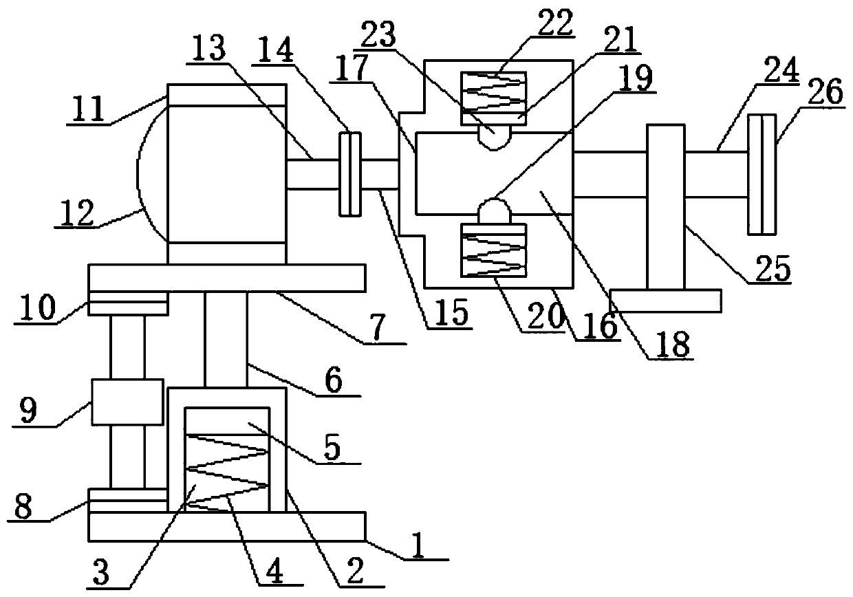
[0019] see figure 1, an embodiment provided by the present invention: includes a bottom fixed base plate 1, a main hollow rod body 2 is installed on one side of the upper surface of the bottom fixed base plate 1, and a main hollow structure 3 is arranged in the center of the main hollow rod body 2, and the A compressed main helical spring 4 is installed inside the main hollow structure 3, a main moving plate 5 is installed on the top of the main helical spring...


PUM


Abstract

The invention discloses a lifting driving device for a wire installation pay-off device. The lifting driving device comprises a bottom fixing baseplate. The lifting driving device couples with a support for the wire installation pay-off device, a power transmission line in a hoisting wheel can neutralize the friction force required by rotation when the end of the power transmission line is pulled,the wire can be subjected to rotation pulling under the premise of low pulling force, and the self-adaptability is improved. The phenomenon of the loosened wire cannot occur, the lifting driving device can control the maximum resistance of rotation, and the phenomenon that the hoisting wheel rotates since the hoisting wheel does not have pulling force is avoided. The lifting driving device is provided with a reverse-thread-structure rotation-type vertical height limit mechanism and can move synchronously with the support for the wire installation pay-off device so as to achieve coupling, in addition, the lifting driving device is provided with a rotation shaft fixing-type part connection mechanism and can achieve a fixing limit function on the rotation shaft and achieve a mounting fixingfunction on the part.

Description

technical field [0001] The invention relates to the technical field of electric power installation, in particular to a lifting drive device for a wire installation pay-off device. Background technique [0002] At present, in the electric power installation site, a pay-off device is needed. The existing pay-off device is driven by a drive motor for rotation. This pay-off device has poor adaptability and requires manpower control. Once the wire is stopped due to traction, the drive motor Continued rotation will often result in loose wire payouts. Contents of the invention [0003] The object of the present invention is to provide a lifting drive device for a wire installation pay-off device to solve the problems raised in the above-mentioned background technology. [0004] In order to achieve the above object, the present invention provides the following technical solution: a lifting drive device for a wire installation pay-off device, including a bottom fixed base plate, a...

Claims


Application Information

Patent Timeline
IPC IPC(8): B65H49/30B65H49/34H02G1/06
CPCB65H49/30B65H49/34B65H2701/34H02G1/06
Inventor 张昕伟
Owner 张昕伟
Why Eureka
Try Eureka