
A grid-like drilling site measurement method for the overlying rock structure of a shallow-buried single key layer stope

A key layer and grid-like technology, which is applied in the field of grid-like drilling field measurement of the overlying rock structure of the shallow-buried single key layer stope, can solve the problem that there is no actual roof structure measurement, it is difficult to grasp the roof rupture and structural movement, and the observation period is long. And other issues

Inactive Publication Date: 2021-07-13
XIAN UNIV OF SCI & TECH
View PDF0 Cites 0 Cited by
  • Summary
  • Abstract
  • Description
  • Claims
  • Application Information

AI Technical Summary

Problems solved by technology

However, the roof structure of the shallow working face is mainly based on the theoretical model proposed by the actual measurement of the support load, physical simulation and numerical calculation, and there is no systematic research on the roof structure.
Most of the actual measurement of the movement of the roof strata at home and abroad is to observe the vertical drilling on the ground of the working face. The cost of vertical drilling is high and the observation period is long. Grasp the broken space position and strength of the working face, but it is difficult to grasp the real situation of the roof crack and structural movement

Method used


Image

  • A grid-like drilling site measurement method for the overlying rock structure of a shallow-buried single key layer stope
  • A grid-like drilling site measurement method for the overlying rock structure of a shallow-buried single key layer stope
  • A grid-like drilling site measurement method for the overlying rock structure of a shallow-buried single key layer stope

Examples


Embodiment Construction

[0044] By the following Figure 1-11B DETAILED DESCRIPTION OF THE PREFERRED EMBODIMENTS, it should be understood that the scope of the invention is not limited by the specific embodiments. Based on the embodiments of the present invention, all other embodiments obtained by those of ordinary skill in the art without making creative labor are the scope of the present invention.

[0045] A mesh-shaped drill field measurement analysis method for shallow-buried single key layers, data source and analysis results, and good results. The present invention adopts the following technical solution:

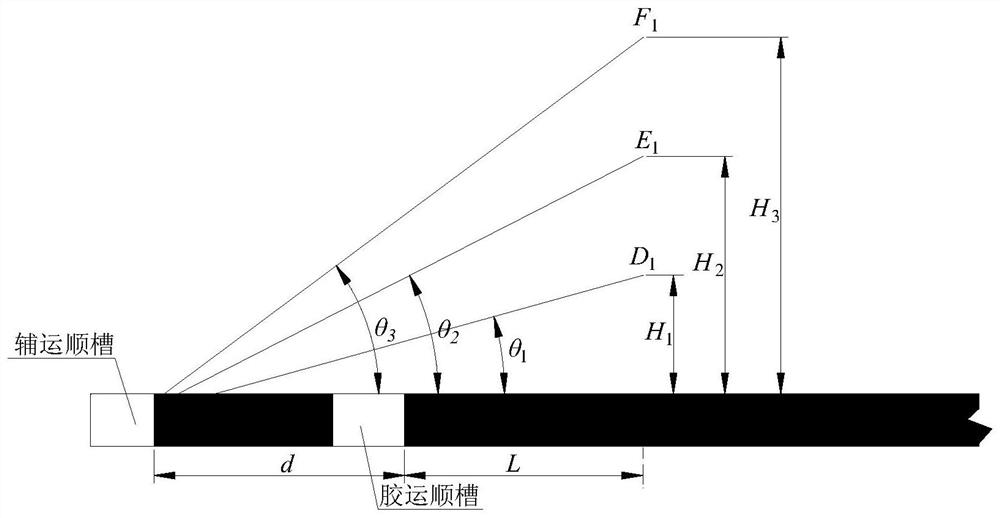
[0046] In order to systematically grasp the interrupting movement process of the shallow meal key layer working surface, the coal-shaped grooves in the working surface, the depth design and construction of multiple sets of drilling (shallow coal-coal seams) , The transport order slot, auxiliary transportation, and returning windshire slots, in space forming a mesh-shaped drill spot ( figure 1 ). ...


PUM


Abstract

The invention discloses a method for actually measuring a grid-shaped drilling field of a shallow-buried single-key layer stope overlying rock structure, and belongs to the technical field of coal mining. The actual measurement method includes setting multiple fixed measuring stations in the auxiliary transportation trough; the boreholes in the return air trough are divided into displacement inclined holes A n , displacement vertical hole B n and peeping oblique hole C n : displacement vertical hole B n with displacement inclined hole A n Located on the same plane, displacement vertical hole B n and displacement inclined hole A n Cross into a net; peep through oblique holes C n Set parallel to the maximum displacement inclined hole; use the auxiliary transportation trough and the return wind trough to arrange the drilling site, and measure the breaking movement track and displacement change law of the roof rock layer. The invention assists the drilling of the transportation along the trough to realize the real-time monitoring of the whole process from pre-mining to post-mining of the working face, and meets the existing observation requirements for the caving zone and crack zone of the roof overlying rock; It is an important source of information for obtaining early-warning and forecasting of working face pressure in the prior art, which is the monitoring for obtaining roof breaking or movement information.

Description

Technical field [0001] The present invention relates to the field of coal mining, and more particularly to a mesh-shaped drill field measurement method for shallow-buried single key layers. Background technique [0002] During the mining of underground coal resources, how to control the activity of overdo is the primary problem. Only the structure of the might formation of the rock body and its activity law can only be reasonable to reasonably use the "bracket-surrounding rock" relationship, the economically controlling the safety, the security of personnel and equipment. The crafting structure is not the artificial structure, and the local observation drilled peeking, the advanced test means, such as sound, microseism, fiber, etc., which expects to obtain the morphological characteristics of the overhang damage. In the laboratory, physical simulation or numerical calculation is used, and the simulated restore train movement is analyzed and deduced by the override structure, anal...

Claims


Application Information

Patent Timeline
Patent Type & Authority Patents(China)
IPC IPC(8): E21C39/00E21C41/18E21F17/18E21F17/00G06Q50/02
CPCE21C39/00E21C41/18E21F17/00E21F17/18G06Q50/02
Inventor 黄庆享贺雁鹏李军刘建浩
Owner XIAN UNIV OF SCI & TECH
Learn More