
Mounting mechanism and nacelle thereof for detecting atmospheric pollution

A mounting and pod technology, which is applied to measurement devices, aircraft parts, fluid velocity measurement, etc., can solve problems such as high cost, local data, and little reference, and achieve simple monitoring methods, easy disassembly, and reference value. high effect

Pending Publication Date: 2020-10-16
SHANGHAI HOCH ENVIRONMENTAL SCI & TECH CO LTD
View PDF0 Cites 0 Cited by
  • Summary
  • Abstract
  • Description
  • Claims
  • Application Information

AI Technical Summary

Problems solved by technology

Atmospheric monitoring is mainly carried out in two ways in the prior art. One is to set up fixed monitoring stations. The data obtained in this way are relatively accurate and low in cost, but the data are only very local and not very informative; the other is to set up fixed monitoring stations. The second is mobile monitoring. At present, monitoring vehicles are mainly used for mobile monitoring. This kind of monitoring data in a large area can be obtained at that time, but the cost is relatively high, and it can only be monitored on the ground. The monitoring data also has great limitations.

Method used


Image

  • Mounting mechanism and nacelle thereof for detecting atmospheric pollution
  • Mounting mechanism and nacelle thereof for detecting atmospheric pollution
  • Mounting mechanism and nacelle thereof for detecting atmospheric pollution

Examples


Embodiment 1

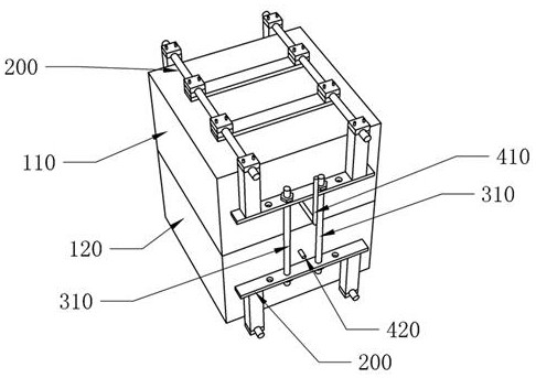
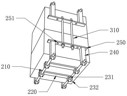
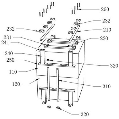
[0063] see Figure 1-5 , the pod of this embodiment, which is mounted on the drone, includes an upper casing 110, a lower casing 120, and a clamp mechanism. The inside of the upper casing 110 is a hollow electrical cavity 111, and the electrical cavity 111 faces downward. One end of the housing 120 is open;

[0064] The end of the lower housing 120 facing the upper housing 110 is provided with an engaging flange 121 , the engaging flange 121 forms an engaging platform 122 with the end surface of the lower housing 120 , and the interior of the lower housing 120 communicates with the electrical cavity 111 The extended electrical chamber 126, the engaging flange 121 is loaded into the upper housing 110 and clamped and assembled with the inner wall of the electrical chamber 111, and the engaging platform 122 is closely attached to the end surface of the upper housing 110, thereby realizing the upper housing Snap fit and fixation between 110 and lower housing 120;

[0065] The cl...

Embodiment 2

[0085] see Figure 6-Figure 16 , the difference between this embodiment and Embodiment 1 is that a mounting mechanism is added, and the connecting device of this embodiment is a buckle assembly 500, and the buckle assembly 500 includes an upper link 311 and a lower link 312, and the upper link 311 One end of the connecting rod 311 is assembled and fixed with the clamp connecting plate 250 of a clamp assembly, and the other end is assembled and fixed with the first connecting block 510;

[0086] The lower connecting rod 312 is assembled and fixed with the clamp connecting plate 250 of another clamp assembly, and the other end is assembled and fixed with the second connecting block 520;

[0087] The upper connecting rod 311 passes through the first connecting block 510, and the second connecting block 520 is provided with a blind slot 522 which is inserted into the end of the upper connecting rod 311, and the first connecting block 510 is also provided with a A buckle 511, a bu...

Embodiment 3

[0104] see Figure 17 , the present embodiment is the monitoring method of the pod in embodiment one and embodiment two, comprising the following steps:

[0105] S1. The monitoring system in the pod is powered on, and each device is initialized;

[0106] S2, the wireless module (GPRS module) establishes a network connection with the ground server or the control host;

[0107] S3. The software built in the controller and the ground server or control host pass key pairing verification to obtain the right to send and receive commands or to exchange data;

[0108] S4. The controller receives the control instructions from the ground server or the control host, and then controls the air pump, nitrogen dioxide sensor, and sulfur dioxide sensor to start working;

[0109] S5, the nitrogen dioxide sensor and the sulfur dioxide sensor collect the nitrogen dioxide and sulfur dioxide data in the airflow sent by the air pump;

[0110] S6. The nitrogen dioxide sensor and the sulfur dioxid...


PUM


Abstract

The invention discloses a mounting mechanism and a nacelle for detecting atmospheric pollution thereof. The mounting mechanism comprises a mounting plate, groove plates and limiting blocks are arranged on the end face, close to an upper shell, of the mounting plate, and a sliding groove is formed between the two groove plates; a first clamping block and a second clamping block are slidably mountedin the sliding groove, the first clamping block and the second clamping block are assembled with a clamping screw rod in a threaded screwing mode, and the screwing directions of the threads where thefirst clamping block and the second clamping block are screwed with the clamping screw rod are opposite. The first clamping block and the second clamping block are provided with a first semi-arc groove and a second semi-arc groove respectively, and the first semi-arc groove and the second semi-arc groove form a clamping round hole assembled with a stress rod in a clamped mode after the first clamping block and the second clamping block are tightly attached; a clamping lug is arranged on the first clamping block; the upper shell is provided with a clamping groove which is assembled with the clamping lug in a clamping manner. According to the invention, a monitoring assembly is arranged in the pod, flow monitoring is achieved in the mode that the unmanned aerial vehicle mounts the nacelle,and the obtained data range is wide, and reference value is high.

Description

technical field [0001] The invention relates to an environment monitoring system, in particular to a mounting mechanism and a pod used for detecting air pollution. Background technique [0002] With the increasing progress of environmental protection concepts and policies and regulations, the monitoring of atmospheric pollutants is now necessary. Atmospheric monitoring is mainly carried out in two ways in the prior art. One is to set up fixed monitoring stations. The data obtained in this way are relatively accurate and low in cost, but the data are only very local and not very informative; the other is to set up fixed monitoring stations. The second is mobile monitoring. At present, monitoring vehicles are mainly used for mobile monitoring. This kind of monitoring data in a large area can be obtained at that time, but the cost is relatively high, and it can only be monitored on the ground. The monitoring data also has great limitations. . [0003] For the above situation,...

Claims


Application Information

Patent Timeline
Patent Type & Authority Applications(China)
IPC IPC(8): B64D47/00G01N33/00G01P5/00
CPCB64D47/00G01N33/0031G01P5/00
Inventor 廖明君
Owner SHANGHAI HOCH ENVIRONMENTAL SCI & TECH CO LTD
Learn More