Water-filtering air purification fan

A technology for purifying fans and air, applied in control input related to air characteristics, air conditioning system, airflow control components, etc., can solve problems such as bad experience, easy blockage of filter, low cost, etc., achieve simple and convenient disassembly and cleaning, and improve human comfort The effect of low degree and manufacturing process requirements

Inactive Publication Date: 2020-07-10
陈明珠
View PDF10 Cites 0 Cited by
  • Summary
  • Abstract
  • Description
  • Claims
  • Application Information

AI Technical Summary

Problems solved by technology

[0002] Fan is a common household appliance in people's daily life. It is deeply loved by people and the market demand has been enduring. The fans of the existing technology on the market can be roughly divided into two categories according to their functions. One category only has the function of ventilation and heat dissipation. This type of fan is low in cost, but has a single function and cannot improve air quality; the other type is a fan with air purification function. The main principle of air purification is to set a layer of single material or multiple layers of different materials at the front of the fan The filter screen is used to block and absorb PM2.5, dust, fluff, pollen and other particulate impurities in the air through the filter screen, so that the air outlet of the fan can output relatively clean air. However, this type of fan has large wind resistance and energy loss. Disadvantages such as large size and easy blockage of the filter, especially after a period of use, the air volume at the air outlet drops significantly, which brings a bad experienc

Method used


Image

  • Water-filtering air purification fan
  • Water-filtering air purification fan
  • Water-filtering air purification fan

Examples


Example Embodiment

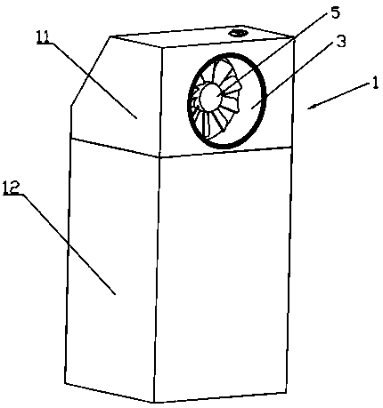
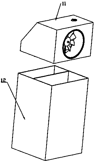
[0046] Such as Figure 1-3 As shown, the water filter air purification fan of the present invention has a housing 1. The housing 1 includes a head housing 11 and a bottom housing 12. The head housing 11 and the bottom housing 12 are constructed in a tool-free, easy-to-disassemble connection manner. As a typical implementation, the present invention uses the head housing 11 to be seated on the bottom housing 12, and the lower end of the head housing 11 is seated on the upper end of the bottom housing 12.

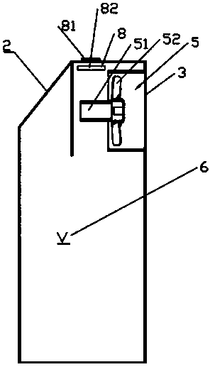
[0047] When the head shell 11 and the bottom shell 12 are connected, the head shell 11 and the bottom shell 12 contain an internal space 6. The head shell 11 is provided with an air inlet 2 and an air outlet 3. The head shell 11 is also provided with a motor fan unit 5 and a control unit 8 for controlling the motor fan unit 5, the motor fan unit 5 is used to drive the air It flows from the air inlet 2 to the air outlet 3 through the internal space 6.

[0048] As a typical impleme...


PUM


Abstract

The invention discloses a water-filtering air purification fan. The water-filtering air purification fan comprises a shell, the shell is provided with an air inlet and an air outlet; a liquid storagepart is arranged in the lower area of the shell, and a motor fan unit is arranged in the upper area of the shell and used for driving air to flow from the air inlet to the air outlet; the shell is contained to form an inner space, and the air inlet is kept in airflow communication with the air outlet through the inner space; and airflow partition plates are arranged in the inner space and divide the inner space into at least three partition chambers, airflow communication is kept among the partition chambers in sequence, and airflow communication is kept between the air inlet and the air outlet through the partition chambers in sequence. The water-filtering air purification fan has the functions of air purification and a fan at the same time, is low in energy loss, good in air purificationeffect, is not prone to blockage a filtering system, low in use cost, easy and convenient to disassemble and clean and suitable for multiple occasions due to the design of the partitioned water filter channel system.

Description

Technical field [0001] The invention relates to a household appliance, in particular to a household appliance device with air purification and ventilation and heat dissipation functions with large flow and high wind speed. Background technique [0002] Fans are a common household appliance in people’s daily life. They are loved by people and the market demand has been enduring for a long time. Fans with existing technology on the market can be roughly divided into two categories according to their functions. One is only with ventilation and heat dissipation. This type of fan has low cost, but has a single function and cannot improve air quality; the other type is a fan with air purification function. The main principle of achieving air purification is to set a single material or multiple layers of different materials at the front of the fan The filter screen is used to block and adsorb particulate impurities such as PM2.5, dust, wool, pollen and so on in the air, so that the fan ...

Claims


Application Information

Patent Timeline
IPC IPC(8): F24F5/00F24F3/16F24F13/20B01D47/02F24F13/08F24F11/88F24F110/50
CPCB01D47/024F24F3/16F24F5/0007F24F13/08F24F13/20F24F11/88F24F2110/50
Inventor 邢长静杨婕妤王睿哲方晨彦
Owner 陈明珠
Why Eureka
Try Eureka