3D acquisition equipment for tiny target object

A technology for collecting equipment and objects, which is applied in the field of shape measurement and 3D shape measurement of tiny objects, can solve the problems of unusable, difficult to accurately determine the angle, and difficult to accurately determine the size, etc., to achieve strong applicability, improve synthesis speed, Ease of use

Active Publication Date: 2020-07-10
天目爱视(北京)科技有限公司
View PDF12 Cites 5 Cited by
  • Summary
  • Abstract
  • Description
  • Claims
  • Application Information

AI Technical Summary

Problems solved by technology

However, in practical applications, it is found that unless there is a precise angle measurement device, the user is not sensitive to the angle, and it is difficult to accurately determine the angle; and when the target object is at the microscopic level, its size is difficult to accurately determine, so that the solution cannot be used on tiny objects. 3D acquisition modeling used in

Method used


Image

  • 3D acquisition equipment for tiny target object
  • 3D acquisition equipment for tiny target object
  • 3D acquisition equipment for tiny target object

Examples


Embodiment Construction

[0035] Exemplary embodiments of the present disclosure will be described in more detail below with reference to the accompanying drawings. Although exemplary embodiments of the present disclosure are shown in the drawings, it should be understood that the present disclosure may be embodied in various forms and should not be limited by the embodiments set forth herein. Rather, these embodiments are provided for more thorough understanding of the present disclosure and to fully convey the scope of the present disclosure to those skilled in the art.

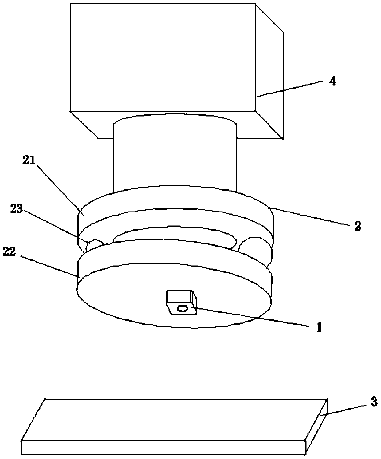
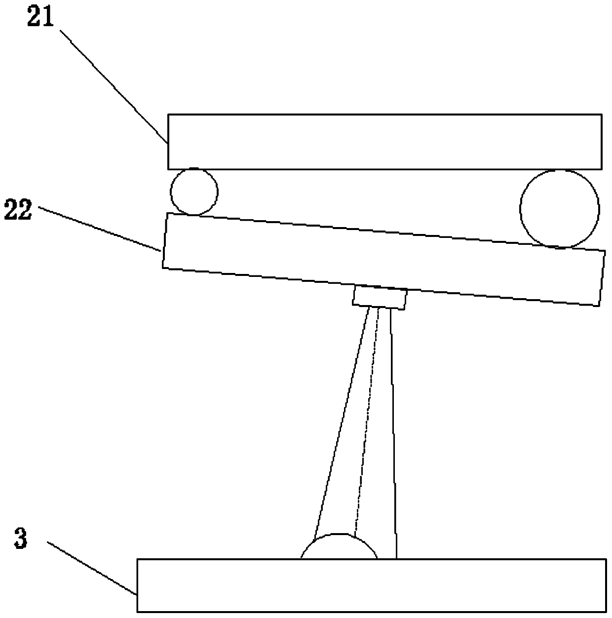
[0036] In order to solve the above technical problems, an embodiment of the present invention provides a 3D collection device for tiny objects, such as figure 1 , including an image acquisition device 1 , a micro-motion device 2 , an object stage 3 , and a driving device 4 .

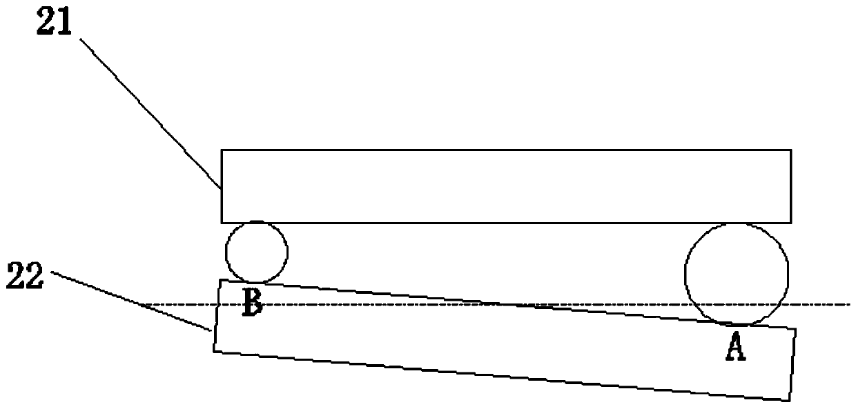
[0037] The micro-motion device includes a turntable 21 and a wobbler 22, two spacers 23 with different diameters are arranged between the turntable 21 and t...


PUM


Abstract

The invention provides acquisition equipment for a tiny target object. The acquisition equipment comprises an image acquisition device, a micro-motion device and an objective table. The micro-motion device comprises a rotary disc and a swing disc, spacers are arranged between the rotary disc and the swing disc, and the spacers rotate along with the rotary disc so as to drive the swing disc to swing near a reference plane. The image acquisition device is arranged on the swing disc. A structure suitable for acquisition around a tiny object is provided for the first time, and the problem of rotating out of view is avoided.

Description

technical field [0001] The invention relates to the technical field of shape measurement, in particular to the technical field of 3D shape measurement of tiny objects. Background technique [0002] At present, when studying cells and microorganisms, traditional microscopes can no longer meet the current needs of stereoscopic observation and measurement because they can only observe plane conditions. However, in current 3D microscopic imaging equipment, confocal imaging is commonly used to form images at different depths, thereby synthesizing 3D images. However, this method usually requires the active emission of laser light or fluorescent light, which may affect living organisms and lead to inaccurate observations. At the same time, due to the layer-by-layer imaging at different depths, the 3D imaging speed is very slow, which is not suitable for living organisms. There is also a way of using lens arrays to split light for multi-focus imaging, but the resolution of this wa...

Claims


Application Information

Patent Timeline
Patent Type & Authority Applications(China)
IPC IPC(8): G01N21/84G01N21/01G06F16/51G06F16/583G06K9/46G06K9/62G06T5/00G06T5/20G06T7/593G06T15/04G06T17/00G06T17/30
CPCG01B11/24G01B9/04G03B35/02G03B17/56G03B17/12
Inventor 左忠斌左达宇
Owner 天目爱视(北京)科技有限公司
Why Eureka
Try Eureka