A silicon-based coupling waveguide adjustable optical delay line and method for adjusting optical delay
A technology of coupling waveguide and delay line, which is applied in the field of adjustable optical delay line and optical delay of silicon-based coupled waveguide, can solve the problems of high cost, complex experimental system, and difficulty in implementation, and achieve stable performance and realize delay. Time and time, the effect that is conducive to integration
- Summary
- Abstract
- Description
- Claims
- Application Information
AI Technical Summary
Problems solved by technology
Method used
Image
Examples
Embodiment Construction
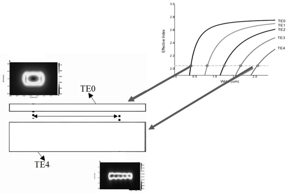
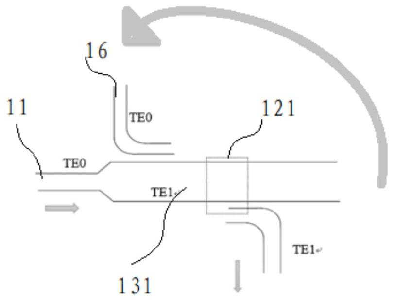
[0023] For ease of understanding, the technical principle of the present invention will be described below first. See figure 2 with image 3 , figure 2 It is a schematic diagram of optical signal jumping between two different waveguides based on the principle of coupled waves. As shown in the figure, the principle of coupled waves is that energy is transferred from one waveguide to another waveguide. In a continuous waveguide, optical signals in different modes, such as from TE0 mode to TE4 mode, energy is transmitted from one part of the waveguide to another part, and the energy of one mode is converted into the energy of another mode. However, when two optical waveguides with different dispersion curves intersect at the phase-matched wavelength node, that is, when the mode-field matching and the effective refractive index are both satisfied, the coupling can only be performed when they are close to each other. figure 2 The coordinate diagram in the upper right part is...
PUM
| Property | Measurement | Unit |
|---|---|---|
| size | aaaaa | aaaaa |
Abstract
Description
Claims
Application Information
 - R&D
- Intellectual Property
- Life Sciences
- Materials
- Tech Scout
- Unparalleled Data Quality
- Higher Quality Content
- 60% Fewer Hallucinations
Browse by: Latest US Patents, China's latest patents, Technical Efficacy Thesaurus, Application Domain, Technology Topic, Popular Technical Reports.
© 2025 PatSnap. All rights reserved.Legal|Privacy policy|Modern Slavery Act Transparency Statement|Sitemap|About US| Contact US: help@patsnap.com


