
Safety control circuit for electromagnetic cooking utensil and electromagnetic cooking utensil

A technology for safety control and cooking utensils, applied to emergency protection circuit devices, circuit devices, emergency protection circuit devices for limiting overcurrent/overvoltage, etc. problems such as high power consumption, to achieve the effect of low circuit cost and simple control

Inactive Publication Date: 2020-07-10
JOYOUNG CO LTD
View PDF8 Cites 0 Cited by
  • Summary
  • Abstract
  • Description
  • Claims
  • Application Information

AI Technical Summary

Problems solved by technology

For the discharge method of the above-mentioned discharge circuit, the former needs to control the switching according to the working state of the rectifier module when the power is off, so as to ensure that the rectifier module switches to the full-wave rectification mode, which may cause the problem of untimely discharge; the latter needs to be connected at both ends of the AC power supply. Parallel discharge resistors, the superposition of the power consumption of the discharge resistor and the power consumption of the whole electromagnetic cooking appliance system makes the power consumption of the whole electromagnetic cooking appliance greater than the standby power consumption requirement, that is, increasing the discharge resistor will increase the power consumption of the whole machine

Method used


Image

  • Safety control circuit for electromagnetic cooking utensil and electromagnetic cooking utensil
  • Safety control circuit for electromagnetic cooking utensil and electromagnetic cooking utensil

Examples


Embodiment Construction

[0031] The technical solutions in the embodiments of the present invention will be clearly and completely described below in conjunction with the accompanying drawings in the embodiments of the present invention. Obviously, the described embodiments are only a part of the embodiments of the present invention, rather than all the embodiments. Based on the embodiments of the present invention, all other embodiments obtained by those of ordinary skill in the art without creative work shall fall within the protection scope of the present invention.

[0032] It should be noted that the terms left, right, up, down, front, and back in the embodiments of the present invention are only relative concepts or refer to the normal use state of the product, that is, the direction of travel of the product. It should not be considered restrictive.

[0033] In the present invention, unless otherwise clearly specified and limited, the terms "installed", "connected", "connected", "fixed" and other ter...


PUM


Abstract

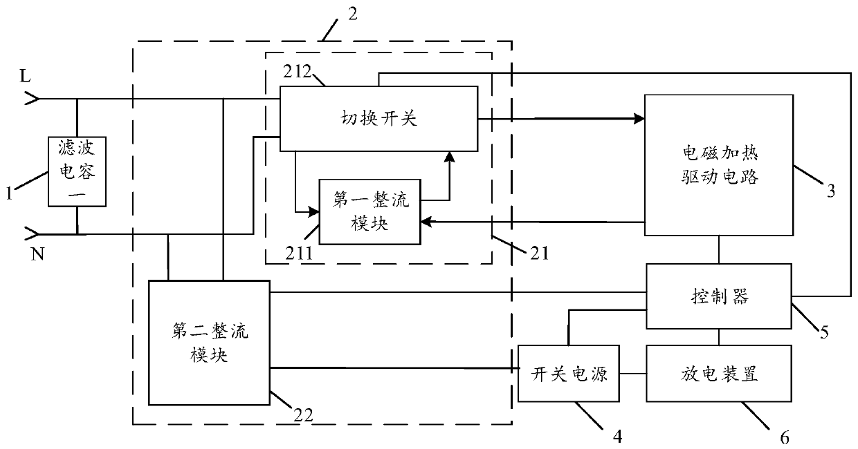
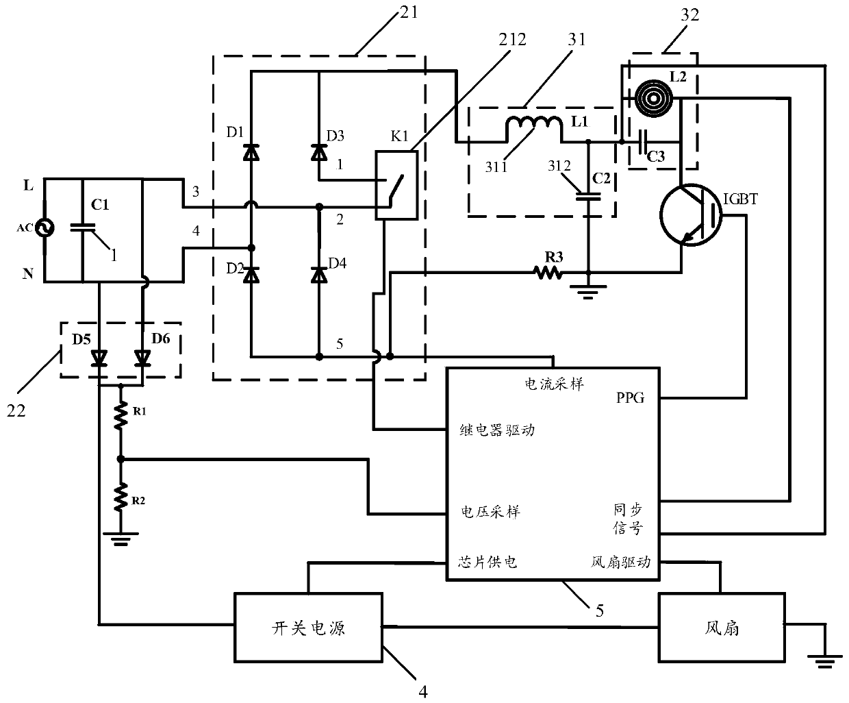
The invention discloses a safety control circuit for an electromagnetic cooking utensil and the electromagnetic cooking utensil. A rectification circuit of the safety control circuit comprises a firstrectification module, a change-over switch and a second rectification module, the first rectification module and the change-over switch form a switchable rectification unit, the output end of the rectification unit is connected with an electromagnetic heating drive circuit, and the output end of the second rectification module is connected with a switching power supply; the switching power supplyis connected with the controller and the discharging device to provide working voltage; the controller is connected with the rectification circuit to collect voltage signals, in case of power failure, the rectifying diode in the first rectification module and the second rectification module are combined to form a discharging rectification unit, and the discharging rectification unit supplies working voltage to the switching power supply, so that residual voltage is released through a discharging device connected with the switching power supply. According to the safety control circuit for theelectromagnetic cooking utensil, discharging can be achieved without connecting discharging resistors to the two ends of the lead connected with the main power source in parallel, and the cost of thedischarging circuit can be reduced.

Description

Technical field [0001] The invention belongs to the technical field of discharge circuits, and in particular relates to a safety control circuit for an electromagnetic cooking appliance and an electromagnetic cooking appliance. Background technique [0002] When the electromagnetic cooking appliance is powered off, because there is still voltage in the power grid, if the residual voltage in the power grid is not discharged in time, some safety accidents that endanger users may occur. [0003] The discharging circuit in the prior art usually controls the rectifier module through a switch. When the circuit system is powered off, it cannot discharge normally in the half-wave rectification mode. Therefore, the rectifier module needs to be switched to the full-wave rectification mode by controlling the switch. Discharge, or connect a discharge resistor in parallel at both ends of the AC power supply to discharge. For the discharge method of the above-mentioned discharge circuit, the fo...

Claims


Application Information

Patent Timeline
Patent Type & Authority Applications(China)
IPC IPC(8): H02H9/04H05B6/12
CPCH02H9/045H05B6/12
Inventor 朱泽春李欣享胡炜张伟
Owner JOYOUNG CO LTD
Learn More