Magneto-thermal isolation type stator structure and motor

A stator structure and isolation technology, applied in the direction of magnetic circuit shape/style/structure, winding insulation shape/style/structure, magnetic circuit, etc., can solve the problems of motor burnout damage, failure to achieve fault-tolerant operation, etc., to achieve improved isolation The ability of heat and magnetic isolation, improving flexibility and improving the effect of slot full rate

Active Publication Date: 2020-07-10
INST OF ELECTRICAL ENG CHINESE ACAD OF SCI
View PDF6 Cites 4 Cited by
  • Summary
  • Abstract
  • Description
  • Claims
  • Application Information

AI Technical Summary

Problems solved by technology

[0005] Therefore, the technical problem to be solved by the present invention is: in the motor structure in the prior art, when a short circuit occurs in any winding wound on the armature teeth, the rest of the windings will be affected, resulting in damage to the motor, which cannot be achieved. fault-tolerant operation

Method used


Image

  • Magneto-thermal isolation type stator structure and motor
  • Magneto-thermal isolation type stator structure and motor

Examples


Embodiment 1

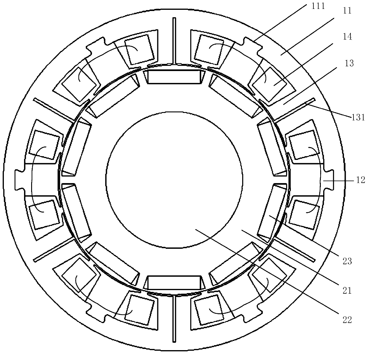
[0045] This embodiment provides a motor, such as figure 1 and figure 2 As shown, it includes: casing, magneto-thermal isolation stator structure and rotor. The casing has an accommodation cavity for accommodating the rotor and the magnetothermally isolated stator structure; the rotor and the magnetothermally isolated stator structure are mutually nested. Specifically, this embodiment takes an inner-rotor motor as an example, and a magnetic-thermal isolation type stator structure is sleeved on the outer side of the rotor.

[0046] In this embodiment, the rotor includes: a rotor core 21 , a rotating shaft 22 and several magnetic steels 23 . Wherein, the rotating shaft 22 is fixedly connected with the rotor core 21, and the magneto-thermal isolation type stator structure is sleeved on the outer periphery of the rotor core 21; the magnetic steel 23 is limited and fixed on the side wall surface of the rotor core 21 facing the magneto-thermal isolation type stator structure supe...

Embodiment 2

[0058] This embodiment provides a motor, which differs from the motor provided in Embodiment 1 in that:

[0059] In an implementation manner in this embodiment, the isolated stator teeth 13 and the stator yoke 11 may be arranged to be plugged into each other.

[0060] In the second implementation of this embodiment, the notch of the isolation slot 131 can be set on the wall surface of the isolated stator tooth 13 facing the coil 14, that is, the side of the isolated stator tooth 13, which can also meet the requirements for the fault heat. isolation.

[0061] Of course, the number of isolated stator teeth 13 can also be any number, and the more the number of isolated stator teeth 13 is, the higher the reliability of isolating the coils 14 on both sides thereof will be.

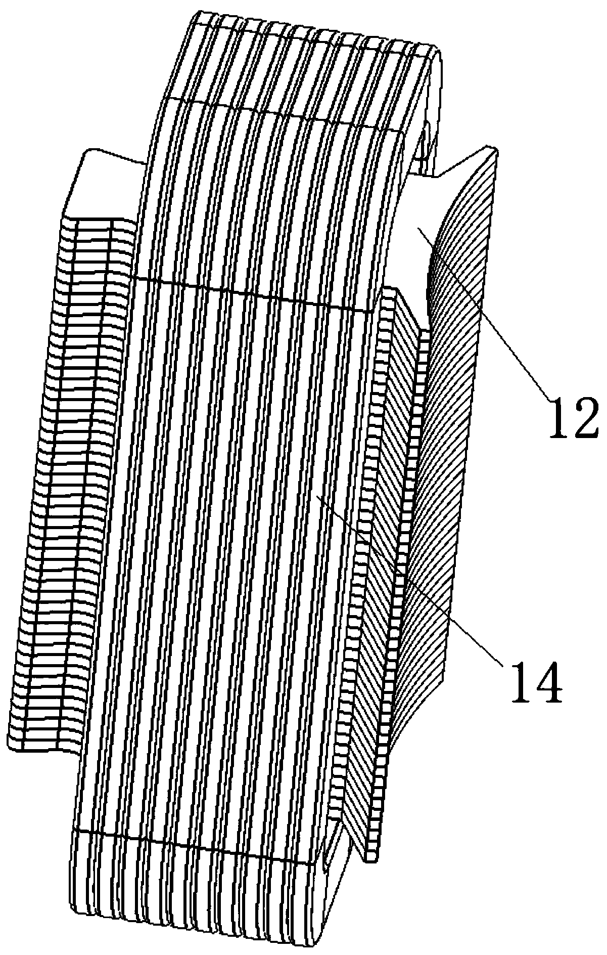
[0062] In the third implementation mode of this embodiment, the stator teeth 12 and the stator teeth 13 are installed in the circumferential direction along the stator yoke 11, and the stator teeth 12 can be i...

Embodiment 3

[0064] This embodiment provides a motor, which differs from the motor provided in Embodiment 1 or Embodiment 2 in that:

[0065] The motor is an external rotor motor, that is, the rotor is arranged outside the magnetothermally isolated stator structure. The stator yoke 11 is provided at the center of rotation, and the rotor core 21 is provided outside the stator yoke 11 . And using the above-mentioned magnetic-thermal isolation type stator structure also realizes the effect of magnetic isolation and heat insulation.


PUM


Abstract

The invention discloses a magneto-thermal isolation type stator structure and a motor. The magneto-thermal isolation type stator structure comprises a stator yoke and a plurality of stator teeth. Wherein the stator yoke and the rotor are sleeved with each other; the stator teeth comprise mounting stator teeth and isolation stator teeth; the mounting stator teeth and the isolation stator teeth arealternately arranged on the circumferential wall surface of one side, close to the rotor, of the stator yoke; any stator tooth protrudes towards one side of the rotor. Winding coils are wound on the peripheries of the mounting stator teeth; the isolation stator teeth are provided with a plurality of isolation grooves, the isolation grooves are recessed from the side close to the rotor to the sideaway from the rotor, and the bottoms of the isolation grooves extend into the stator yoke. Winding phase-to-phase thermal field isolation is achieved, and therefore the phase-to-phase thermal isolation effect is achieved when a motor operates in a fault mode. Moreover, the inter-phase mutual inductance of the windings is effectively reduced, and the self-inductance of the windings is increased, sothat the influence of a fault winding short-circuit magnetic field on the normal winding magnetic performance is shielded, and the inter-phase electromagnetic field isolation effect of the windings during motor fault operation is further improved.

Description

technical field [0001] The invention relates to the technical field of magnetothermal isolation of motors, in particular to a magnetothermal isolation type stator structure and a motor. Background technique [0002] The permanent magnet motor has good mechanical characteristics and excellent torque characteristics. The fractional slot concentrated winding permanent magnet motor has the advantages of high efficiency, high torque density and compact end space. Ensure that the positioning torque of the permanent magnet motor is small and the torque fluctuation is small. It is widely used in direct drive occasions with compact space. In the above-mentioned application occasions, the permanent magnet motor is an important source of power, and it has high requirements on the fault tolerance of the motor. Therefore, the fractional slot concentrated winding motor has the characteristics of low mutual inductance between windings and the ability of electromagnetic isolation between w...

Claims


Application Information

Patent Timeline
Patent Type & Authority Applications(China)
IPC IPC(8): H02K1/12H02K1/14H02K1/16H02K3/34H02K1/27
CPCH02K1/12H02K1/146H02K1/165H02K1/2706H02K3/345H02K2213/03
Inventor 李琦范涛温旭辉李晔王佐梁
Owner INST OF ELECTRICAL ENG CHINESE ACAD OF SCI
Why Eureka
Try Eureka