Positioning method and system based on ultra-wideband technology

A technology of ultra-wideband technology and positioning method, applied in positioning, radio wave measurement system, measuring device, etc., can solve the problems of poor positioning accuracy, high cost, limited application range, etc., achieve high-precision location services, and reduce the cost of the whole machine Power Consumption, Effects of Continuous Location Services

Active Publication Date: 2020-07-10
北京金坤科创技术有限公司
View PDF14 Cites 3 Cited by
  • Summary
  • Abstract
  • Description
  • Claims
  • Application Information

AI Technical Summary

Problems solved by technology

In such complex environmental scenarios, the combination of WiFi technology, Bluetooth technology, Zigbee technology, or micro-inertial navigation technology can usually provide a positioning accuracy of 3-5 meters in a good signal coverage area, but the indoor environment is much more complicated. The reliability of positioning and navigation in indoor scenes is severely challenged, and the positioning accuracy will become worse. It is an urgent problem to be solved to provide high-precision sub-meter positioning solutions in indoor environments.
At the same time, in the outdoor environment, GNSS enhancement technology based on dual-frequency GNSS technology, or RTK, RTD technology can improve outdoor positioning accuracy, but its outdoor application is due to the immaturity of dual-frequency chips, the deployment of ground enhancement stations, and equipment power consumption. Due to size and other issues, its application scope is still limited, and the cost of GNSS enhancement technology based on RTK and RTD is still high, and there is greater resistance to consumer-level applications

Method used


Image

  • Positioning method and system based on ultra-wideband technology
  • Positioning method and system based on ultra-wideband technology
  • Positioning method and system based on ultra-wideband technology

Examples


Embodiment 1

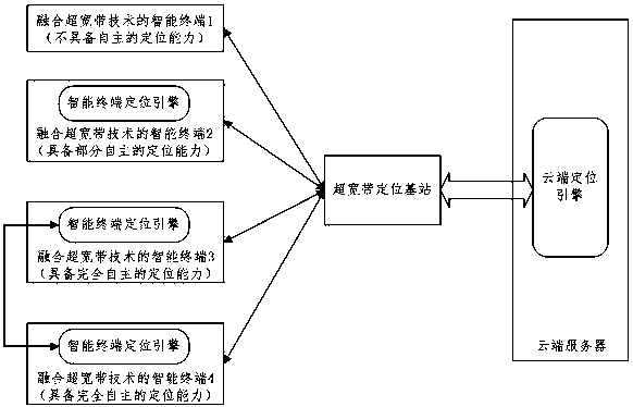
[0035] Embodiment 1 is aimed at Case 1 described in the Summary of the Invention, that is, an intelligent terminal that does not have an autonomous positioning capability. In Embodiment 1, a typical smart terminal (smart terminal 1) without autonomous positioning capability is characterized in that: the number of antennas used by the terminal for positioning calculation is 1, and only supports time-of-flight ranging, but does not support Azimuth measurement.

[0036] The signaling process of Embodiment 1 is as follows (such as figure 2 shown):

[0037] Step 201: The intelligent terminal 1 without autonomous positioning capability sends positioning capability reporting information to the ultra-wideband positioning base station;

[0038]Step 202: After the ultra-wideband positioning base station receives the capability reporting information of the terminal, it feeds back the positioning capability reporting confirmation information to the smart terminal 1;

[0039] Step 203:...

Embodiment 2

[0046] Embodiment 2 is aimed at Case 2 described in the Summary of the Invention, that is, an intelligent terminal with partially autonomous positioning capability. However, it belongs to a branch situation in Case2, that is, the smart terminal calculates the location information by itself after passing the judgment. In Embodiment 2, a typical intelligent terminal (smart terminal 2) with partial autonomous positioning capability is characterized in that: the terminal has two antennas for positioning calculation, supports time-of-flight ranging, and supports horizontal plane ( Orientation angle measurement within -π / 2, π / 2).

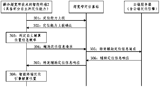
[0047] The signaling flow of Embodiment 2 is as follows (such as image 3 shown):

[0048] Step 301: The intelligent terminal 2 with partial autonomous positioning capability sends positioning capability reporting information to the ultra-wideband positioning base station;

[0049] Step 302: After the ultra-wideband positioning base station receives th...

Embodiment 3

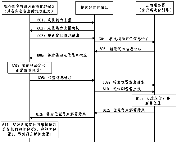
[0057] Embodiment 3 is aimed at Case 2 described in the Summary of the Invention, that is, an intelligent terminal with partially autonomous positioning capability. However, it belongs to another branch of Case2, that is, after the smart terminal passes the judgment, it needs the network to provide the final location information solution. In Embodiment 3, a typical intelligent terminal (intelligent terminal 2) with partial autonomous positioning capability is characterized in that: the terminal has two antennas for positioning calculation, supports time-of-flight ranging, and supports horizontal plane ( Orientation angle measurement within -π / 2, π / 2).

[0058] The signaling process of Embodiment 3 is as follows (such as Figure 4 shown):

[0059] Step 401: The intelligent terminal 2 with partial autonomous positioning capability sends positioning capability reporting information to the ultra-wideband positioning base station;

[0060] Step 402: After receiving the capabilit...


PUM


Abstract

The invention discloses a positioning method and system based on an ultra-wideband technology. The core idea of the positioning method is that the intelligent terminal fused with the ultra-wideband technology reports the positioning capability based on the ultra-wideband technology to a network side or performs positioning capability interaction with other intelligent terminals. And the network side provides corresponding types of positioning auxiliary information or positioning results according to different positioning capabilities of different intelligent terminals so as to realize high-precision positioning of the intelligent terminals. The positioning system is composed of an intelligent terminal fused with the ultra-wideband technology, a network side positioning base station, an intelligent terminal positioning engine and a cloud positioning engine. According to the invention, the positioning capability of the intelligent terminal can be fully excavated, reliable and continuoushigh-precision position service is provided for the intelligent terminal, and the method has a wide application prospect in the fields of Internet of Things, Internet of Vehicles, unmanned aerial vehicles, unmanned driving and the like.

Description

technical field [0001] The invention relates to the field of positioning based on ultra-wideband technology. Background technique [0002] With the continuous development of satellite positioning systems, various civil service scenarios based on satellite positioning have been mature and widely used, such as navigation applications of Baidu and AutoNavi, and car services of Didi Taxi. However, this kind of application mainly solves the navigation and positioning of outdoor personnel and vehicles, and the positioning accuracy is usually 5-10 meters in the urban environment. [0003] However, people's demand for location-based services still has great space and potential. Location information is the most basic element in the Internet of Things era. In the indoor environment, people's rigid needs for navigation and positioning often exist in parking space navigation and reverse car search, or location navigation services in viewing areas of large sports venues, etc. In such c...

Claims


Application Information

Patent Timeline
Patent Type & Authority Applications(China)
IPC IPC(8): H04W64/00G01S5/00
CPCH04W64/00G01S5/0027
Inventor 吴彤唐珂贺媛肖登坤
Owner 北京金坤科创技术有限公司
Why Eureka
Try Eureka