
Main and auxiliary cavity coupling type self-adaptive cyclone centrifugal degassing method and device

A degassing device, coupled technology, applied in the direction of a cyclone device, a device whose axial direction of the cyclone can be reversed, etc., can solve the problem of increased energy consumption, increased separation difficulty, and degassing efficiency not greater than 90%, etc. problems, to achieve the effect of improved degassing efficiency, advanced separation time, and rapid and sufficient separation

Active Publication Date: 2020-07-14
EAST CHINA UNIV OF SCI & TECH +1
View PDF4 Cites 8 Cited by
  • Summary
  • Abstract
  • Description
  • Claims
  • Application Information

AI Technical Summary

Problems solved by technology

If simply relying on reducing the diameter of the cyclone and increasing the tangential velocity to generate stronger liquid phase turbulence, the behavior of the multi-scale bubble group will be more difficult to predict, and the breakup of the bubbles will increase the difficulty of separation and increase the energy consumption
Using a traditional gas-liquid separator with a single swirl radius to degas the above-mentioned gas-liquid mixture containing multi-scale bubble groups, the degassing efficiency is usually not more than 90%, and the energy consumption increases
[0012] Therefore, traditional gas-liquid separators and separation methods with a single swirl radius can no longer meet the separation requirements for multi-scale bubbles in liquids.

Method used


Image

  • Main and auxiliary cavity coupling type self-adaptive cyclone centrifugal degassing method and device
  • Main and auxiliary cavity coupling type self-adaptive cyclone centrifugal degassing method and device
  • Main and auxiliary cavity coupling type self-adaptive cyclone centrifugal degassing method and device

Examples


Embodiment 1

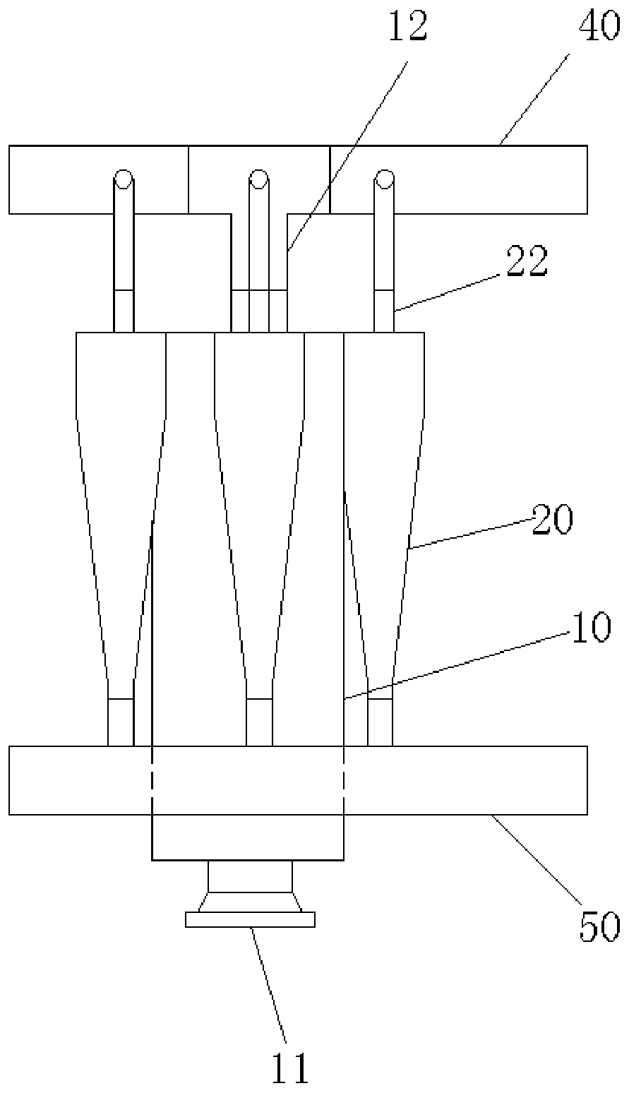
[0077] Such as Figure 1 to Figure 6 As shown, the main and auxiliary cavity coupled adaptive cyclone centrifugal degassing device of this embodiment has a basic structure including a main cyclone 10, five auxiliary cyclones 20, and connecting the main cyclone 10 and the auxiliary cyclone 5 coupling channels 30 of the device 20; wherein:

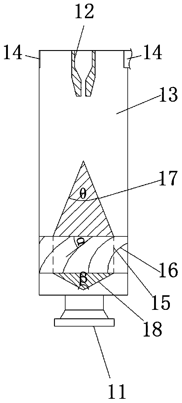
[0078] The main cyclone 10 is a cylindrical structure, the bottom of the main cyclone 10 is provided with an axial-flow type main cyclone inlet 11, the top is provided with an overflow pipe 12, and there is a main cyclone cavity 13 inside, A diversion structure is installed in the main swirl cavity 13, and five tangential liquid outlets 14 are arranged tangentially and uniformly on the side wall of the upper part of the main swirl 10;

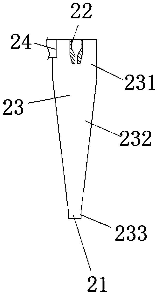
[0079] The secondary cyclone 20 is a column-conical structure, the bottom of the secondary cyclone 20 is provided with a secondary cyclone outlet 21, the top is provided with an overflow pipe 22, and there i...

Embodiment 2

[0097] Such as Figure 7 shown. The basic structure of the main-sub-chamber coupled self-adaptive cyclone centrifugal degasser in this embodiment is the same as that of Embodiment 1, the difference is that the rotation direction of the material in the secondary cyclone chamber is the same as that of the material in the main cyclone chamber. The rotation directions are opposite, and the number of the secondary swirlers 20 and the coupling channels 30 is four.

Embodiment 3

[0099] The basic structure of the main and auxiliary cavity coupled adaptive cyclone centrifugal degassing device of this embodiment is the same as that of Embodiment 1, the difference lies in the structure of the overflow pipe. in particular:

[0100] Such as Figure 8 As shown, the inner cavity of the overflow pipe (12,22) includes an upper cylindrical cavity (121,221), an upper conical cavity (122,222), a lower cylindrical cavity (123,223) and a lower conical cavity (124,224) connected in sequence; The apex angles of the upper conical cavity (122, 2212) and the lower conical cavity (124, 224) are the same, the apex of the upper conical cavity (122, 222) faces downward, and the apex of the lower conical cavity (124, 224) faces upward. The cone tip angle γ of the upper conical cavity (122, 222) and the lower conical cavity (124, 224) is 20-40°.

[0101] In this way, the cone top of the upper conical chamber (122, 2212) faces downwards, and gradually expands upward to form a...


PUM

PropertyMeasurementUnit
Diameteraaaaaaaaaa
Viscosityaaaaaaaaaa
Viscosityaaaaaaaaaa

Abstract

The invention discloses a main and auxiliary cavity coupling type self-adaptive cyclone centrifugal degassing method. The main and auxiliary cavity coupling type self-adaptive cyclone centrifugal degassing method comprises the following steps: (1) a gas-liquid mixture enters a main cyclone cavity for hydrocyclone separation, and under the action of a centrifugal force, larger bubbles flow out froman overflow pipe at the top of the main cyclone, and the liquid containing a small amount of fine bubbles enters auxiliary cyclone cavities from tangential liquid inlets after passing through coupling channels; and (2) hydrocyclone separation is performed on the liquid containing the small amount of fine bubbles in the auxiliary cyclone cavities, and under the action of the centrifugal force, thefine bubbles flow out from the overflow pipes at the top of the auxiliary cyclones, and the degassed liquid flows out from the discharge ports of the auxiliary cyclones. The number of the coupling channels has a one-to-one correspondence with the number of the auxiliary cyclones, and the number is at least 2; the coupling channels and the auxiliary cyclones are evenly distributed along the outercircumference of the main cyclone; and the ratio of the centrifugal acceleration of the liquid in the auxiliary cyclones to the centrifugal acceleration of the liquid in the main cyclone is (5 to 100)to 1. The main and auxiliary cavity coupling type self-adaptive cyclone centrifugal degassing method and device disclosed by the invention have high separation efficiency and high degassing efficiency.

Description

technical field [0001] The invention belongs to the technical field of gas-liquid separation. In particular, it relates to a primary and secondary chamber coupling type self-adaptive cyclone centrifugal degassing method and device. Background technique [0002] Liquid entrained gas in nature and industrial production is a common phenomenon, and the demand for liquid degassing exists widely in the fields of environmental protection, metallurgy and petrochemical industry. The gas entrained in the liquid not only causes foaming of the fluid, vibration of the pump valve, and damage to the production equipment, but also causes fugitive gas emission pollution, oxygen-enriched water environment, affects the accuracy of the detection instrument, and increases the analysis error. Therefore, it is necessary to pass the gas-liquid The separation device separates the gas in the liquid, that is, degasses the liquid. [0003] At present, cyclone degassing technology has been widely rese...

Claims


Application Information

Patent Timeline
IPC IPC(8): B04C5/26B04C5/107B04C5/12B04C5/081B04C5/185
CPCB04C5/26B04C5/107B04C5/12B04C5/081B04C5/185
Inventor 许萧杨强王俊杰钱运东王磊王威
Owner EAST CHINA UNIV OF SCI & TECH
Learn More