Welding fixture for high-low voltage power distribution cabinet production

A technology for welding fixtures and power distribution cabinets, applied in welding equipment, auxiliary welding equipment, welding/cutting auxiliary equipment, etc., can solve the problems of manpower consumption and low efficiency, achieve fast fixing speed, improve efficiency, and improve welding efficiency Effect

Active Publication Date: 2020-07-14
ANHUI HETIAN ELECTRIC
View PDF13 Cites 6 Cited by
  • Summary
  • Abstract
  • Description
  • Claims
  • Application Information

AI Technical Summary

Problems solved by technology

[0005] The purpose of the present invention is to solve the problem of labor-intensive and low efficiency in

Method used


Image

  • Welding fixture for high-low voltage power distribution cabinet production
  • Welding fixture for high-low voltage power distribution cabinet production
  • Welding fixture for high-low voltage power distribution cabinet production

Examples


Embodiment 1

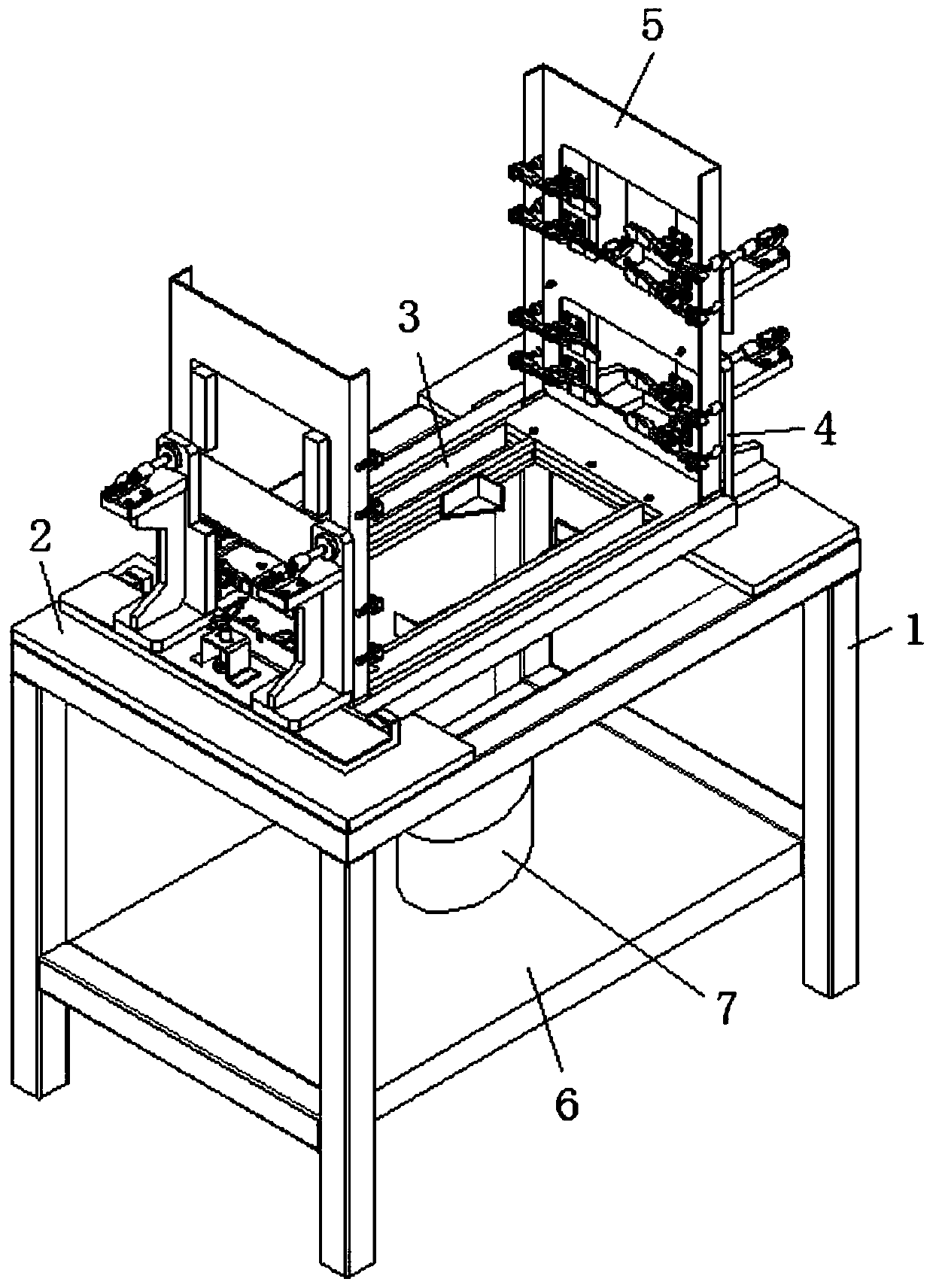
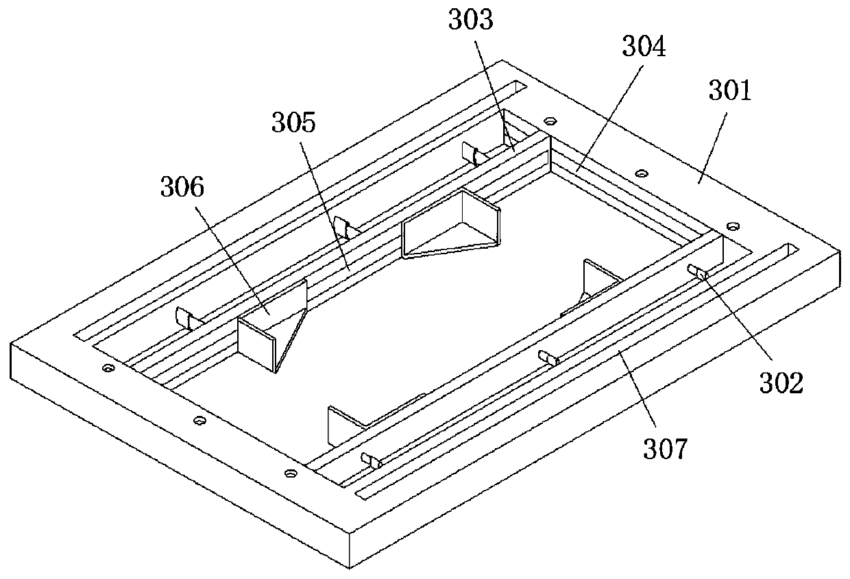
[0029] refer to Figure 1-4 , a welding fixture for the production of high and low voltage power distribution cabinets, including a fixing frame 1, mounting plates 2 are fixedly connected to both sides of the top surface of the fixing frame 1, and a holding mechanism 3 is fixedly connected to the top surfaces of the two mounting plates 2. Mechanism 3 includes a rectangular frame 301, the front and rear end inner walls of the rectangular frame 301 are fixedly connected with electric telescopic rods 302, and the telescopic ends of the electric telescopic rods 302 at the same end are all connected with support bars 303 by screws, and the two sides of the support bar 303 are connected with the rectangular frame 301. The inner walls are connected by sliding contact, and the two support bars 303 are provided with adjustment grooves 305 at one end close to each other. There are right-angle fixing blocks 306 slidingly connected in the adjustment grooves 305, and there are two right-ang...

Embodiment 2

[0033] Such as figure 1 and 4 As shown, this embodiment is basically the same as Embodiment 1. Preferably, the rotating mechanism includes a support plate 6, the middle part of the top surface of the support plate 6 is fixed with a servo motor 7 through screws, and the output end of the servo motor 7 is fixed with a mounting plate through screws. Block 8, a cylinder 9 is affixed to the top surface of the installation block 8, and an electromagnet 10 is affixed to the output end of the cylinder 9.

[0034] In this embodiment, the adjustment of the position of the electric control cabinet can be realized through the cylinder 9, so as to facilitate the rotation operation of the electric control cabinet, and further realize the comprehensive welding operation of the electric control cabinet.

Embodiment 3

[0036] Such as figure 1 and 4 As shown, this embodiment is basically the same as Embodiment 1. Preferably, the support plate 6 is fixed on the fixed frame 1, and the input ends of the servo motor 7 and the cylinder 9 are electrically connected to the controller, and the top surface of the electromagnet 10 horizontal setting.

[0037] In this embodiment, by electrically connecting the input terminals of the servo motor 7 and the cylinder 9 to the controller, it is convenient to control the working states of the servo motor 7 and the cylinder 9, thereby realizing automatic production.


PUM


Abstract

The invention discloses a welding fixture for high-low voltage power distribution cabinet production. The welding fixture comprises a fixing frame, mounting plates are fixedly connected to two sides of the top face of the fixing frame respectively, a containing mechanism is fixedly connected to the top faces of the two mounting plates, the containing mechanism comprises a rectangular frame, and electric telescopic rods are fixedly connected to the inner walls of the front end and the rear end of the rectangular frame respectively; supporting strips are fixedly connected to the telescopic endsof the electric telescopic rods at same ends through screws, two sides of each supporting strip are in sliding contact connection with the inner wall of the rectangular frame, adjusting grooves are formed in the ends, close to each other, of the two supporting strips, two right-angle fixing blocks are slidably connected into each adjusting groove, sliding grooves are further formed in the front side and the rear side of the top face of the rectangular frame, and vertical plates are arranged on two sides of the rectangular frame. The welding fixture is reasonable in design, capable of achievingrapid fixing of electric control cabinet plates of different specifications, wide in application range and high in fixing speed of the electric control cabinet plates, and the electric control cabinet welding work efficiency is greatly improved.

Description

technical field [0001] The invention relates to the technical field of production equipment for high and low voltage distribution cabinets, in particular to a welding fixture for production of high and low voltage distribution cabinets. Background technique [0002] As the name implies, the high and low voltage power distribution cabinet is the power distribution equipment used for power distribution, control, measurement and cable connection in the power supply system. Generally, power supply bureaus and substations use high voltage switch cabinets, which are produced in high and low voltage power distribution cabinets. It is often necessary to weld straight plates, which requires welding fixtures. [0003] After retrieval, the patent application number 201920714490.X discloses a non-standard fixture for sheet metal welding, including a base and a movable plate. The front and back of the top of the base are respectively provided with rectangular slots, and the insides of th...

Claims


Application Information

Patent Timeline
IPC IPC(8): B23K37/04H02B3/00
CPCB23K37/04B23K2101/36H02B3/00
Inventor 朱世俊黄春志朱世明
Owner ANHUI HETIAN ELECTRIC
Why Eureka
Try Eureka