Drilling liner cementing tool with packer and cementing method

A liner cementing and packer technology, which is applied in the field of oil and gas well drilling and completion, can solve the problems of easy encountering resistance, limitation of open pump circulation pressure, and the inability of packer to play annulus isolation, so as to reduce the The risk of leakage, improving the success rate of running, improving the success rate of running and the effect of cementing quality

Pending Publication Date: 2020-07-14
BC P INC CHINA NAT PETROLEUM CORP +1
View PDF0 Cites 6 Cited by
  • Summary
  • Abstract
  • Description
  • Claims
  • Application Information

AI Technical Summary

Problems solved by technology

[0002] At present, the sidetracking well liner cementing in Changqing Oilfield mainly adopts the pack-off hydraulic liner hanger, and the main problems in the application process are as follows: 1. The sidetracking well cementing operation is a typical slim hole narrow gap cementing, and the casing running process It is easy to encounter obstruction in the middle, and the circulation pressure of the pump is limited after the conventional hydraulic liner hanger encounters obstruction (the general method for unblocking is to circulate the drilling fluid). If the circulation pressure exceeds the shear pressure of the hydraulic cylinder shear nail, the hanger will sit and hang in advance , the casing string cannot be lowered to the design position; 2. The conventional packer hydraulic liner hanger packer is set using a mechanical principle, that is, the weight of the drilling tool is used to squeeze the packer to make the seal Radial deformation of the rubber barrel of the device can achieve the purpose of annular space sealing
However, if the suspension position is high and the weight of the drilling tool cannot meet the setting requirements of the packer, the original packer will not be able to effectively isolate the annulus

Method used


Image

  • Drilling liner cementing tool with packer and cementing method
  • Drilling liner cementing tool with packer and cementing method

Examples


Embodiment 1

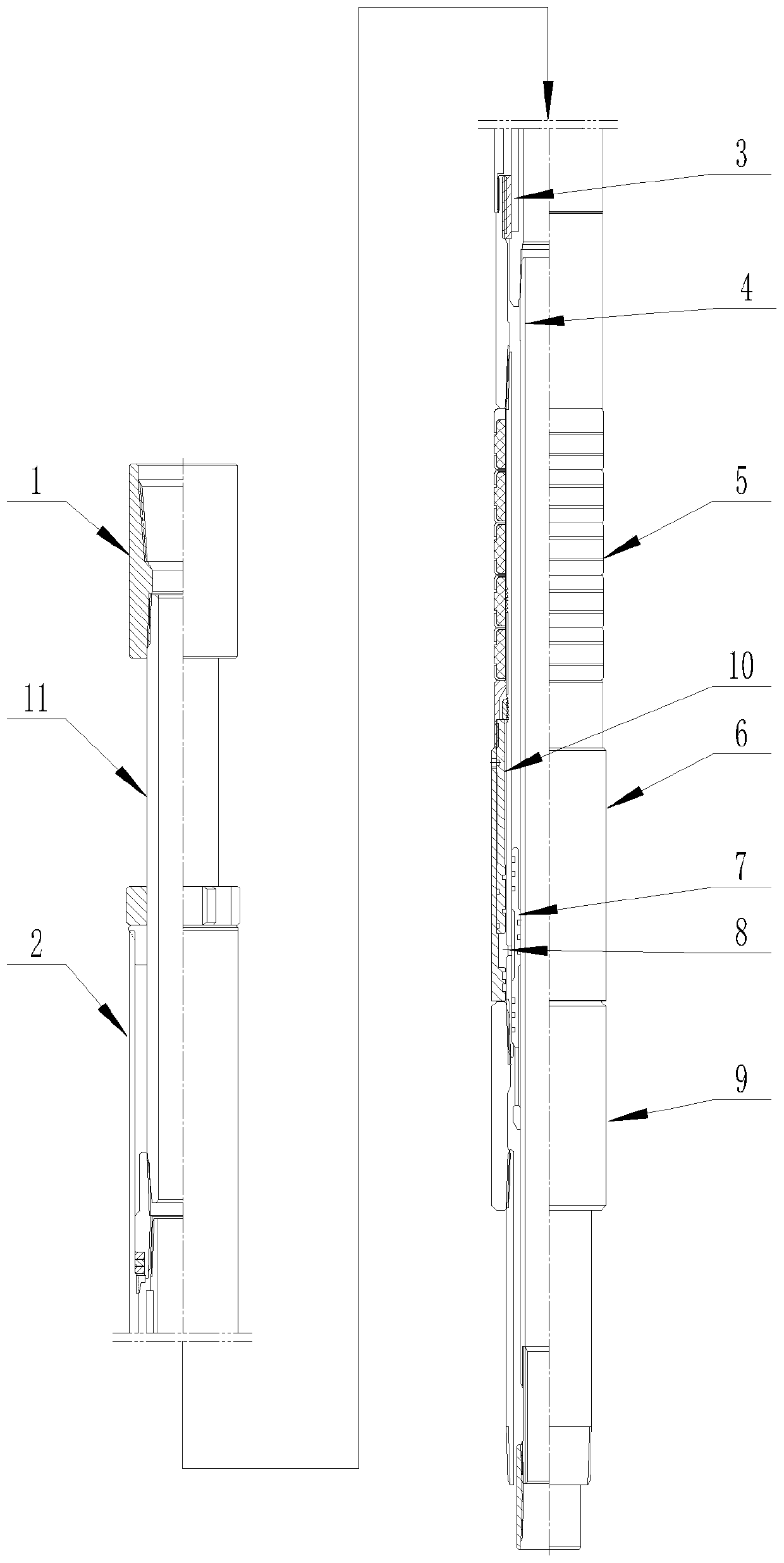
[0033] refer to figure 1 , is a structural schematic diagram of Embodiment 1 of the present invention, a liner cementing tool with a packer, including

[0034] Tool body 10;

[0035] The central core pipe 4, the central core pipe 4 is socketed in the tool body 10;

[0036] Drill pipe joint 1;

[0037] Lifting sub 11, one end of the lifting sub 11 is connected with the drill pipe joint 1, and the other end of the lifting sub 11 is connected with the core pipe 4;

[0038] The reverse screw sleeve 3, the reverse screw sleeve 3 is connected to the outer wall of the lifting nipple 11 connected with the core tube 4, and the core tube 4 is socketed in the tool body 10 through the reverse screw sleeve 3;

[0039] Tie-back barrel 2, the tie-back barrel 2 is connected to the outer wall of the top of the tool body 10;

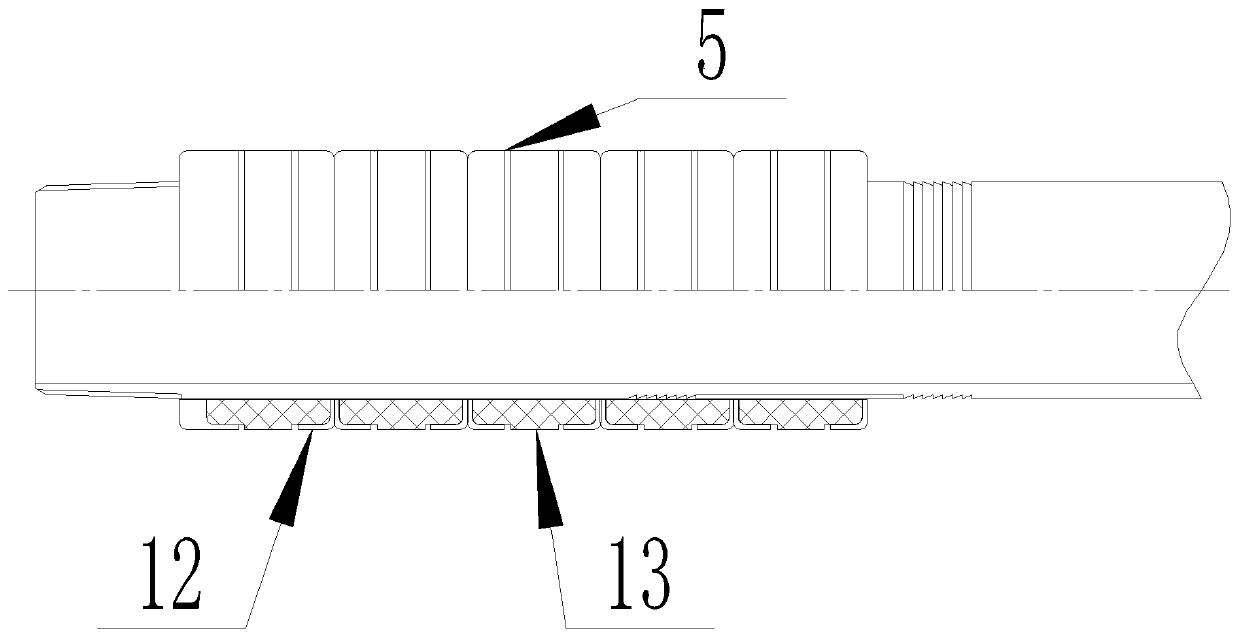
[0040] A packer 5, the packer 5 is connected to the outer wall of the tool body 10 at the lower end of the tie-back barrel 2;

[0041] A hydraulic cylinder 6, the hy...

Embodiment 2

[0045] Compared with Embodiment 1, the difference of this embodiment is that: the outer wall of the core tube 4 where the tool body 10 and the core tube 4 are socketed is connected with a sealing sleeve 7 .

[0046] During actual use: the sealing sleeve 7 acts as a movable seal after losing hands, so as to ensure the successful implementation of the cementing operation.

Embodiment 3

[0048] Compared with Embodiment 1, the difference of this embodiment is that: there is a liquid inlet hole 8 between the inner wall of the tool body 10 and the inner cavity of the hydraulic cylinder 6 .

[0049] In actual use: the liquid inlet hole 8 is set between the inner wall of the tool body 10 and the inner cavity of the liquid cylinder 6, so as to ensure that the liquid enters the liquid cylinder 6 when the central tube 4 is lifted up, and avoids when the central tube 4 is not lifted up. Liquid just enters liquid cylinder 6.


PUM


Abstract

The invention relates to the technical field of oil-gas well drilling completion technology, in particular to a drilling liner cementing tool with a packer and a cementing method. Hydraulic setting ofthe packer is carried out after a well is cemented through the drilling liner cementing tool, safety and reliability are achieved, the requirement of later underground increasing production operationis met, the drilling liner cementing tool with the packer is fed in the drilling rig in-well process, pumping circulation can be carried out in the whole process, circulating pressure is not limitedby pump pressure, and the sleeve lowering success rate is improved. Compared with a general hydraulic drilling liner hanger, an annular clearance of the drilling liner cementing tool and an upper sleeve is large in the cementing process, the circulation is reduced, the risk of leakage is reduced, the problems of dropout, borehole collapse and the like due to a ball seat of a general hanger generates surge pressure are solved, and the lowering success rate and the cementing quality of the whole drilling liner cementing tool are improved through the cementing method.

Description

technical field [0001] The invention relates to the technical field of oil and gas well drilling and completion, in particular to a liner cementing tool with a packer and a cementing method. Background technique [0002] At present, the sidetracking well liner cementing in Changqing Oilfield mainly adopts the pack-off hydraulic liner hanger, and the main problems in the application process are as follows: 1. The sidetracking well cementing operation is a typical slim hole narrow gap cementing, and the casing running process It is easy to encounter obstruction in the middle, and the circulation pressure of the pump is limited after the conventional hydraulic liner hanger encounters obstruction (the general method for unblocking is to circulate the drilling fluid). If the circulation pressure exceeds the shear pressure of the hydraulic cylinder shear nail, the hanger will sit and hang in advance , the casing string cannot be lowered to the design position; 2. The conventional ...

Claims


Application Information

Patent Timeline
Patent Type & Authority Applications(China)
IPC IPC(8): E21B33/13E21B33/126
CPCE21B33/126E21B33/13
Inventor 刘志雄王文斌陈小荣欧阳勇陈兴中刘克强陈宁李志宏周文兵陈财政唐凯王勇茗杜松涛高果成朱哲段成才
Owner BC P INC CHINA NAT PETROLEUM CORP
Why Eureka
Try Eureka