
A measurement system for thermal field distribution of sonic nozzle pipe wall

A sonic nozzle and measurement system technology, applied in the direction of measuring heat, measuring devices, thermometers using electric/magnetic elements that are directly sensitive to heat, etc., can solve the problem of large environmental changes in the temperature measurement system, insufficient temperature measurement steps, and Problems such as limited temperature range

Active Publication Date: 2021-04-27
TIANJIN UNIV
View PDF7 Cites 0 Cited by
  • Summary
  • Abstract
  • Description
  • Claims
  • Application Information

AI Technical Summary

Problems solved by technology

[0003] At present, the measurement and reconstruction of the temperature field on the wall surface of the sonic nozzle are mostly carried out by means of contact with traditional temperature sensors, or non-contact temperature measurement by infrared thermometers. The above-mentioned temperature measurement methods can reflect the temperature of the nozzle wall to a certain extent. However, the temperature measurement system is greatly affected by environmental changes, the temperature measurement range is limited and it is difficult to obtain detailed pipe wall temperature information, and the temperature measurement steps are not systematic enough

Method used


Image

  • A measurement system for thermal field distribution of sonic nozzle pipe wall
  • A measurement system for thermal field distribution of sonic nozzle pipe wall
  • A measurement system for thermal field distribution of sonic nozzle pipe wall

Examples


Embodiment Construction

[0023] In order to further illustrate the features, operation process, specific advantages and performances of the present invention, the present invention will be described in detail below in conjunction with the accompanying drawings and specific embodiments.

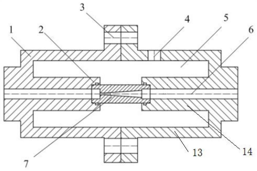
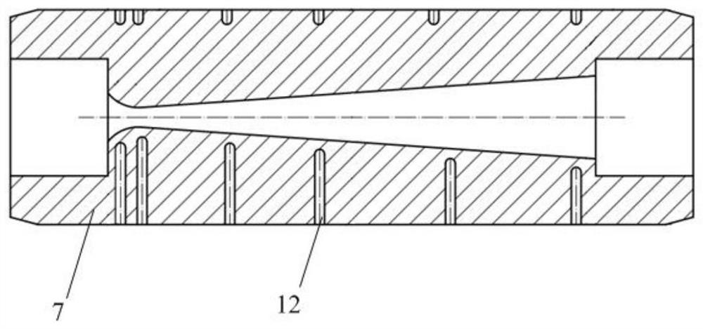
[0024] see figure 1 , the stable installation of the sonic nozzle 7 is a precondition for measuring the temperature field of the pipe wall, so in the present invention, a design such as figure 1 The shown nozzle heat insulation fixture 1 is used to assist in fixing the sonic nozzle, and can also help the nozzle 7 to better connect with the fluid channel 6 . The main material of the heat insulation fixture 1 is PVC material, which has heat insulation effect. The fixture device is divided into two symmetrical parts, which can be assembled or disassembled through the nuts on the flange plate 3, so that the nozzle 7 can be replaced or the heat insulation fixture can be removed. 1 has become more convenient. O-shaped rub...


PUM


Abstract

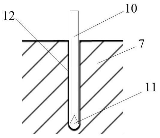
The invention relates to a thermal field distribution measurement system of a sonic nozzle pipe wall, which includes an adiabatic fixture for clamping a sonic nozzle in a fluid channel, and a miniature thermocouple array for collecting the section temperature of a sonic nozzle, and the adopted sonic nozzle is made of metal In this way, the heat-insulating fixture is made of heat-insulating material, including two fixture units that can be disassembled and can be fixedly connected together, each fixture unit includes a fixture shell and a clamping column located on the axis of the fixture, and the clamping column The middle part of the body is provided with a through fluid channel, and the ends of the clamping cylinders of the two clamp units are respectively sealed and connected with one end of the sonic nozzle, so that the sonic nozzle is fixed on the axis of the heat insulating fixture and communicated with the fluid channel. After the fixture unit is fixedly connected, an annular gap is formed between the fixture shell and the clamping cylinder; thermocouple implantation holes with different positions and different depths are provided on the body of the sonic nozzle for implanting a thermocouple sensor array.

Description

technical field [0001] The invention relates to a sonic nozzle pipe wall thermal field distribution measurement system belonging to the field of gas flow detection. Background technique [0002] Sonic nozzle is one of the most commonly used flow sensors, which are widely used in the field of flow measurement, and have the characteristics of reliable performance, simple structure, and high accuracy level. However, due to the structural characteristics of the sonic nozzle itself, the flow rate of the gas in the nozzle will continue to increase, the volume of the gas will continue to expand, and with the decrease of the gas temperature, the heat transfer between the low-temperature gas and the wall of the sonic nozzle will cause the temperature of the nozzle wall to change, and then Adversely affect the performance of the sonic nozzle. With the application of sonic nozzles in aerospace technology, medical field, petroleum processing and other fields, the research on the perfor...

Claims


Application Information

Patent Timeline
Patent Type & Authority Patents(China)
IPC IPC(8): G01K7/02G01K7/13G01K1/14G01K1/16
CPCG01K7/02G01K7/13G01K1/14G01K1/16G01K2219/00
Inventor 丁红兵梁真馨曹培娟
Owner TIANJIN UNIV
Learn More