A device and method for observing micro-droplets

A micro-droplet and micro-channel technology, applied in measurement devices, optical devices, chemical instruments and methods, etc., can solve the problems of high price, limited CCD sampling frame rate, difficult integration, etc., and achieve easy construction and comprehensive information acquisition. , the effect of low cost

Active Publication Date: 2019-02-19
SHANGHAI INST OF MICROSYSTEM & INFORMATION TECH CHINESE ACAD OF SCI
View PDF5 Cites 0 Cited by
  • Summary
  • Abstract
  • Description
  • Claims
  • Application Information

AI Technical Summary

Problems solved by technology

[0004] (a) Observing micro-droplets by using a conventional CCD image sensor; the disadvantage of this method is: due to the limited sampling frame rate of CCD, it is difficult to directly observe high-throughput (high-speed motion) micro-droplets and obtain micro-droplets Information
[0005] (b) By using a high-speed camera to shoot the motion process of the micro-droplets in the microfluidic channel, the relevant information of the micro-droplets can be obtained through image analysis; the disadvantages of this method are: expensive, difficult to integrate, and difficult to measure the droplets in real time parameters
[0006] (c) Infer the information of micro-droplets by using photodetector tubes to detect the optical signals sent by micro-droplets; the disadvantage of this method is that it is difficult to obtain the information of micro-droplets comprehensively, and it is usually only applicable to the counting of droplets

Method used


Image

  • A device and method for observing micro-droplets
  • A device and method for observing micro-droplets
  • A device and method for observing micro-droplets

Examples


Embodiment Construction

[0035] Below in conjunction with the drawings, preferred embodiments of the present invention are given and described in detail.

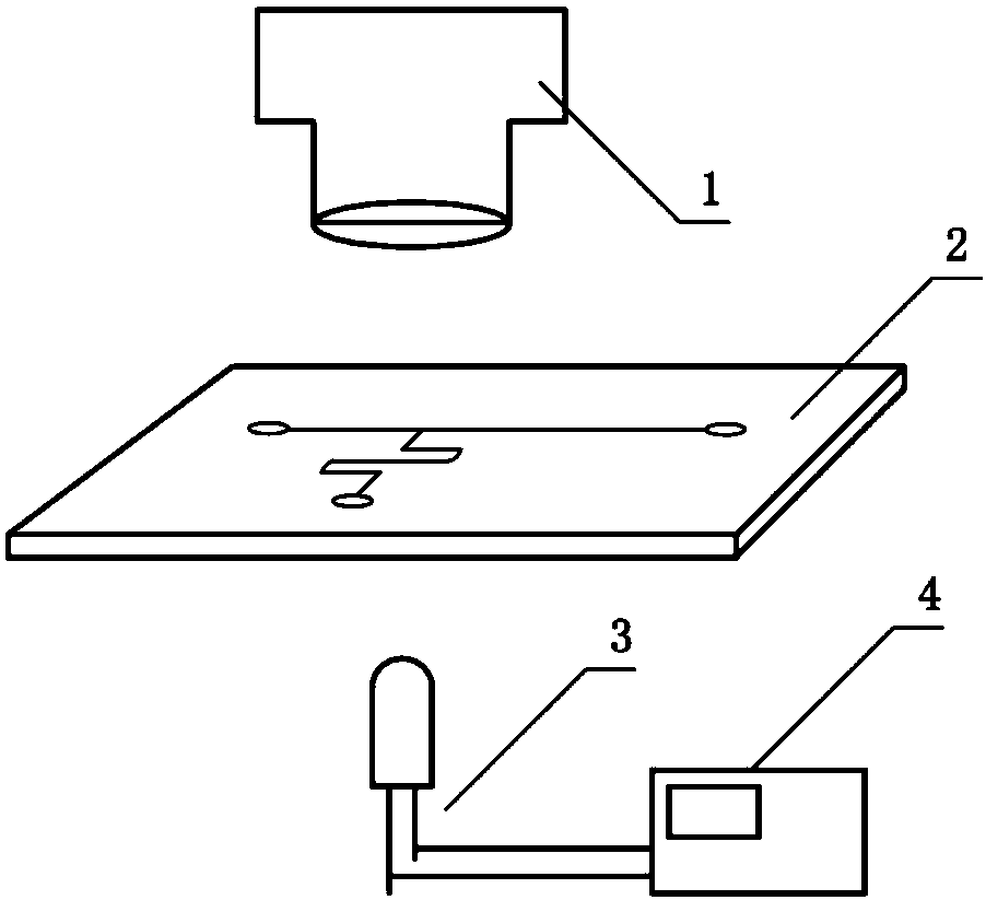
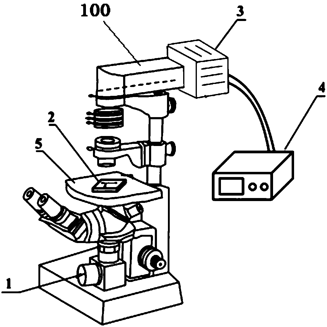
[0036] Such as Figure 1-5 As shown, one of the present invention, that is, a device for observing microdroplets, includes: an image acquisition module 1, a microfluidic chip 2, a scintillation light source 3, and a scintillation light source control module 4 connected to the scintillation light source 3; In the example, an OlympusI X51 type microscope 100 is used as a platform, an image acquisition module 1 is externally connected to the image acquisition port of the microscope 100, the microfluidic chip 2 is placed on the stage 5 of the microscope 100, and the scintillation light source 3 and the scintillation light source The control module 4 is externally connected to the light source entrance of the microscope 100 .

[0037] The image acquisition module 1 can adopt a conventional low frame rate (10-100 frames per second) image acquisition sys...


PUM

PropertyMeasurementUnit
volumeaaaaaaaaaa
volumeaaaaaaaaaa
diameteraaaaaaaaaa

Abstract

The invention relates to a device for observing microdroplets, which includes: a microfluidic chip, which has a microchannel containing periodically moving microdroplets; a flashing light source, which is generated according to a control signal provided by a flashing light source control module. flickering light with preset flickering parameters; and an image acquisition module, which collects images of micro-droplets in the micro-channel of the microfluidic chip irradiated by the scintillation light. In the present invention, the flickering light source is controlled by the flickering light source control module to generate flickering light of a specific frequency, and irradiates the microfluidic chip; then the image acquisition module collects the images on the microfluidic chip; the microfluidic liquid can be obtained through these images and the frequency of the flickering light. Droplet size, shape and flux and other information. Compared with traditional methods such as high-speed cameras and photoelectric tubes, the present invention has the advantages of comprehensive information acquisition, convenience, low cost, and easy construction, and can be widely used in miniaturized microfluidic systems.

Description

technical field [0001] The invention relates to a device and a method for observing micro-droplets, in particular to a device and method for observing micro-droplets in microfluidics aimed at high-throughput and periodic micro-droplets. Background technique [0002] Microfluidic chip (microfluidic chip), also known as lab on a chip, refers to the integration or basic integration of basic operating units such as sample preparation, reaction, separation, and detection involved in the fields of biology and chemistry. On a chip of a few square centimeters (or even smaller), a network of microchannels is formed, and a controllable fluid runs through the entire system to replace various functions of conventional biological or chemical laboratories. So far, microfluidic chip technology has begun to be applied in different fields of life sciences. Recently, droplet-based microfluidics has attracted increasing attention. Compared with microchannels, microdroplets have the following...

Claims


Application Information

Patent Timeline
Patent Type & Authority Patents(China)
IPC IPC(8): G01N21/84G01N21/63G01B11/00G01B11/24H04N5/235B01L3/00
CPCG01B11/00G01B11/24G01N21/63G01N21/84B01L3/5027G01N2201/061H04N23/745
Inventor 周洪波刘松生毛红菊金庆辉赵建龙
Owner SHANGHAI INST OF MICROSYSTEM & INFORMATION TECH CHINESE ACAD OF SCI
Why Eureka
Try Eureka