
Permanent magnet motor capable of rapid cooling

A permanent magnet motor, fast technology, applied in the direction of electromechanical devices, electrical components, electric components, etc., can solve the problem of poor cooling effect, achieve good cooling effect, fast flow rate, increase heat exchange effect

Active Publication Date: 2020-07-14
CHONGQING UNIV OF ARTS & SCI
View PDF7 Cites 4 Cited by
  • Summary
  • Abstract
  • Description
  • Claims
  • Application Information

AI Technical Summary

Problems solved by technology

[0005] The present invention intends to provide a fast-cooling permanent magnet motor to solve the problem of poor cooling effect of the rotor of the existing permanent magnet motor

Method used


Image

  • Permanent magnet motor capable of rapid cooling
  • Permanent magnet motor capable of rapid cooling
  • Permanent magnet motor capable of rapid cooling

Examples


Embodiment 1

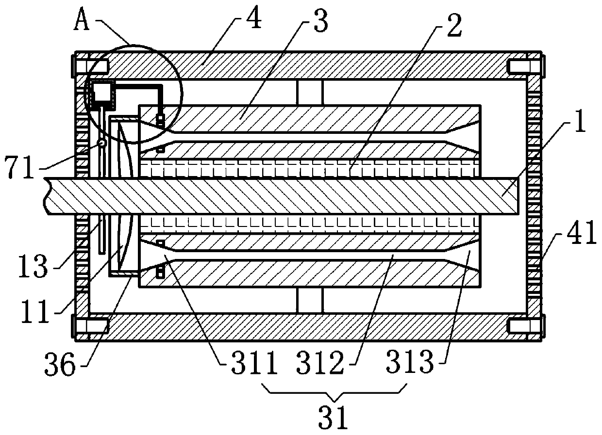
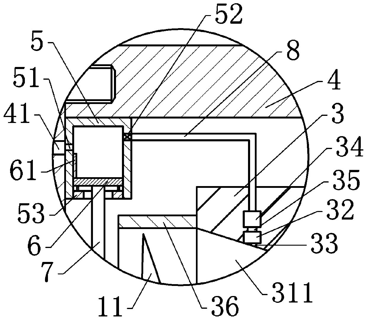
[0038] A permanent magnet motor with rapid cooling, basically as attached figure 1 As shown, it includes a drive shaft 1, a rotor 2, a stator 3, and a casing 4 arranged in sequence from the inside to the outside. The rotor 2 is a permanent magnet, and a fixed block is welded on the outside of the stator 3. The side of the fixed block away from the stator 3 is welded to the casing. 4 inside. The casing 4 includes a casing wrapped around the stator 1 and end caps installed on both sides of the casing. The end caps are provided with a plurality of air holes 41, and the end caps are fixed on the casing by bolts. by figure 1 The view of , the left side of the shell 4 is the front end, and the right side of the shell 4 is the rear end.

[0039] The front end of the drive shaft 1 passes through the front end cover, and the front end of the drive shaft 1 extends out of the end cover, and the drive shaft 1 is rotatably connected to the front end cover. The front end of the drive sha...

Embodiment 2

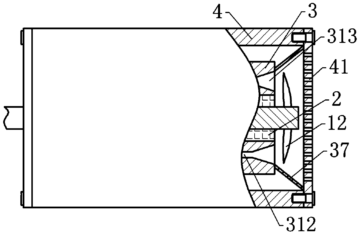
[0052] Embodiment 2 differs from Embodiment 1 only in that, as image 3 As shown, the rear end of the stator 3 is welded with a second windshield 37, and the second windshield 37 wraps four air guide passages 31; the second windshield 37 is conical, and the second windshield 37 is large The diameter end faces right, and the right end of the second windshield 37 abuts against the end cover on the right side. Three second rotating blades 12 are welded on the rear end of the drive shaft 1, and the three second rotating blades 12 form the structure of fan blades, so that when the second rotating blades 12 rotate, the gas on the front side is sucked in and discharged to the rear side .

[0053] During the operation of the motor, the drive shaft 1 drives the second rotating blade 12 to rotate, so that the rotation of the second rotating blade 12 generates a flow of gas, which quickly sucks the gas in the air guide channel 31 and discharges it to the right. During this process, the...


PUM


Abstract

The invention belongs to the technical field of motors with channels or pipelines for flowing of cooling media, and discloses a permanent magnet motor capable of rapidly cooling. The motor comprises adriving shaft, a rotor, a stator and a shell which are sequentially arranged from inside to outside, wherein the stator is fixed in the shell, a plurality of air holes are formed in the shell, the front end of the driving shaft extends out of the shell, a plurality of air guide channels are formed in the stator in the axial direction, each air guide channel comprises a flow guide section, a cooling section and a leading-out section which are sequentially arranged away from the front end of the driving shaft, and the flow guide sections and the leading-out sections are conical; the small-diameter ends of the flow guide sections and the lead-out sections have the same diameter as the cooling sections and are communicated with the cooling sections; and a first rotating blade for guiding airto the flow guide sections is further fixed to the part, located in the shell, of the front end of the driving shaft. The problem of poor rotor cooling effect of an existing permanent magnet motor issolved.

Description

technical field [0001] The invention belongs to the field of motors with passages or pipes for cooling medium flow, and in particular relates to a permanent magnet motor with rapid cooling. Background technique [0002] A motor is an electromagnetic device that converts or transmits electrical energy according to the law of electromagnetic induction. It usually includes a stator, a rotor wrapped outside the stator, and a casing wrapped outside the rotor. There are many types of motors, among which the permanent magnet motor is a common one. The permanent magnet motor uses permanent magnets as the rotor to generate a rotating magnetic field, so that the three-phase stator windings can induce three-phase symmetrical currents through the armature reaction under the action of the rotating magnetic field. motor. [0003] After the permanent magnet motor is used for a long time, its driving system (ie, the permanent magnet) will generate a lot of heat, and the driving system work...

Claims


Application Information

Patent Timeline
IPC IPC(8): H02K5/20H02K9/06H02K1/20
CPCH02K1/20H02K5/20H02K9/06H02K2205/09
Inventor 梁康有谭宇航肖天伦温慧慧
Owner CHONGQING UNIV OF ARTS & SCI
Learn More