
Surface overlaying method of thin-walled metal

A surface surfacing and metal technology, applied in metal processing equipment, welding equipment, welding accessories, etc., can solve the problems of thin-walled metal back burn-through, excessive oxidation, metal internal medium leakage, etc., to avoid excessive metal temperature, The effect of reducing the dwell time and reducing the welding swing amplitude

Active Publication Date: 2020-07-17
LINGAO NUCLEAR POWER +5
View PDF4 Cites 1 Cited by
  • Summary
  • Abstract
  • Description
  • Claims
  • Application Information

AI Technical Summary

Problems solved by technology

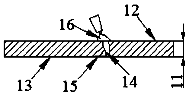
[0003] Please refer to figure 1 Shown, suffer metal wall thickness 11 (spacing between metal overlay welding surface 12 and metal backside 13) less influence, there is following defect in existing surface overlay welding method: one, welding arc 16 when welding, welding The penetration depth of the seam is large, which is easy to cause metal breakdown14 caused by the welding heat source; second, the high heating temperature of the metal is easy to cause quality problems such as oxidation15 and burning of the metal backside13
In particular, for pipelines with water, oil, gas and other media with a certain internal pressure, improper welding methods will lead to production accidents such as leakage of metal internal media.
[0004] In view of this, it is necessary to provide a thin-walled metal surface surfacing method to avoid quality problems such as back burn-through and excessive oxidation of thin-walled metals

Method used


Image

  • Surface overlaying method of thin-walled metal
  • Surface overlaying method of thin-walled metal
  • Surface overlaying method of thin-walled metal

Examples


Embodiment Construction

[0032] In order to make the purpose, technical solution and beneficial technical effects of the present invention clearer, the present invention will be further described in detail below in conjunction with the accompanying drawings and specific embodiments. It should be understood that the specific implementations described in this specification are only for explaining the present invention, not for limiting the present invention.

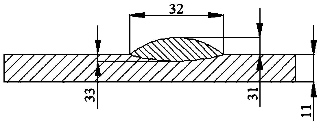
[0033] Please refer to Figures 2 to 5 Shown, the surface welding method of thin-walled metal of the present invention comprises the following steps:

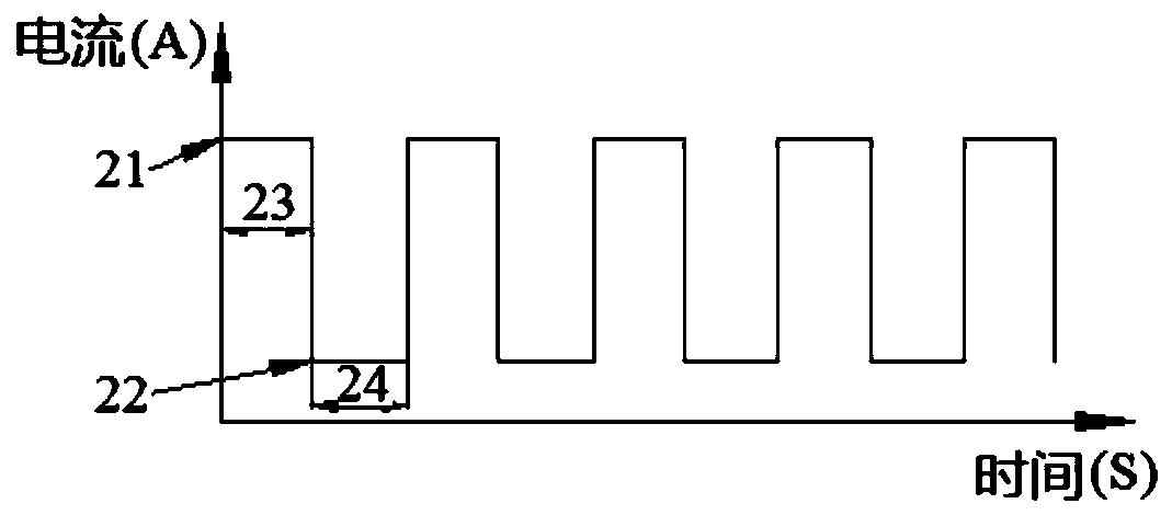
[0034] 1) Select a power supply that can realize peak-valley current output, and obtain a welding bead that meets the requirements by adjusting the peak current, peak current time, valley current, and valley current time;

[0035] 2) completing the welding of different welding passes in sequence to form a welding layer; and

[0036] 3) Repeat step 2) to complete the welding of different welding l...


PUM

PropertyMeasurementUnit
Thicknessaaaaaaaaaa
Thicknessaaaaaaaaaa

Abstract

The invention discloses a surface overlaying method of thin-walled metal. The surface overlaying method of the thin-walled metal comprises the following steps that (1) a power source capable of achieving peak current-valley current output is selected, and by adjusting a peak current, the time of the peak current, a valley current and the time of the valley current, weld beads meeting requirementsare obtained; (2) welding of different weld beads is sequentially completed, so that a weld layer is formed; (3) the step (2) is repeatedly executed, welding of different weld layers is sequentially completed, and then welding of all the weld layers is completed. Compared with the prior art, the surface overlaying method of the thin-walled metal utilizes the power source with the peak current-valley current switching feature to avoid the situation that the peak current continuously heats the surface of the metal and causes the temperature of the metal to be excessively high, and the quality problems of burning through of the back face of the metal, excessive oxidization and the like can be avoided.

Description

technical field [0001] The invention belongs to the field of welding technology, more specifically, the invention relates to a thin-walled metal surface surfacing method. Background technique [0002] At present, in actual production, there are many cases where surfacing treatment is required due to metal surface or shallow surface defects. [0003] Please refer to figure 1 Shown, suffer metal wall thickness 11 (spacing between metal overlay welding surface 12 and metal backside 13) less influence, there is following defect in existing surface overlay welding method: one, welding arc 16 when welding, welding The seam penetration is large, which is likely to cause metal breakdown 14 caused by the welding heat source; second, the high heating temperature of the metal is likely to cause quality problems such as oxidation 15 and burning of the metal back 13. In particular, for pipelines with water, oil, gas and other media with a certain internal pressure, improper welding met...

Claims


Application Information

Patent Timeline
IPC IPC(8): B23K9/04B23K9/235B23K9/32
CPCB23K9/042B23K9/235B23K9/32
Inventor 李心刚匡艳军郑超雄孙志强范岩成张志明熊志亮苏锋杰张发云周骁凌张建林郭凯唐利萍张蕾李守彬邓小云姚祥宏
Owner LINGAO NUCLEAR POWER
Learn More