
Lathe for machining inner slope of valve seat and using method thereof

A technology of inclined plane and valve seat, which is applied in the direction of metal processing equipment, metal processing machinery parts, turning equipment, etc., can solve the problems of troublesome adjustment, unstable structure, affecting work efficiency, etc., and achieve high convenience, stable structure, and convenient adjustment Effect

Active Publication Date: 2020-07-17
浙江诚昌机械配件有限公司
View PDF5 Cites 7 Cited by
  • Summary
  • Abstract
  • Description
  • Claims
  • Application Information

AI Technical Summary

Problems solved by technology

The valve seat can be processed by a lathe. Some valve seats have a sloped inner hole, and the axis of the inner hole and the axis of the valve seat have a certain offset. Processing, when processing a workpiece that needs to be turned at both ends, it needs to be clamped twice, which affects the work efficiency and easily causes the deviation of the coaxiality of the two ends of the workpiece, which cannot meet the requirements of use. The existing lathe tool holder is adjusting The height is achieved by adding or reducing gaskets at the bottom of the tool holder. This method requires a large number of gaskets, which is very troublesome to adjust. At the same time, the structure is unstable. When the parts are processed, it is necessary to spray coolant on the workpiece and the tool. , the coolant spraying device of the existing lathe cannot recycle the sprayed coolant, resulting in waste of coolant, and the lathe will continuously produce iron chips when it is working. Although there is an iron chip outlet on the bottom of the lathe, when the iron If the swarf does not fall in time and accumulates too much at the iron filing outlet, it will cause blockage and affect the normal operation of the lathe. When processing workpieces, the headstock will generate heat, especially when the speed is fast. If the heat cannot be dissipated in time, it will greatly Reduced headstock life, necessitating improvements to existing lathes

Method used


Image

  • Lathe for machining inner slope of valve seat and using method thereof
  • Lathe for machining inner slope of valve seat and using method thereof
  • Lathe for machining inner slope of valve seat and using method thereof

Examples


Embodiment Construction

[0043]The following will clearly and completely describe the technical solutions in the embodiments of the present invention with reference to the accompanying drawings in the embodiments of the present invention. Obviously, the described embodiments are only some, not all, embodiments of the present invention. Based on the embodiments of the present invention, all other embodiments obtained by persons of ordinary skill in the art without creative efforts fall within the protection scope of the present invention.

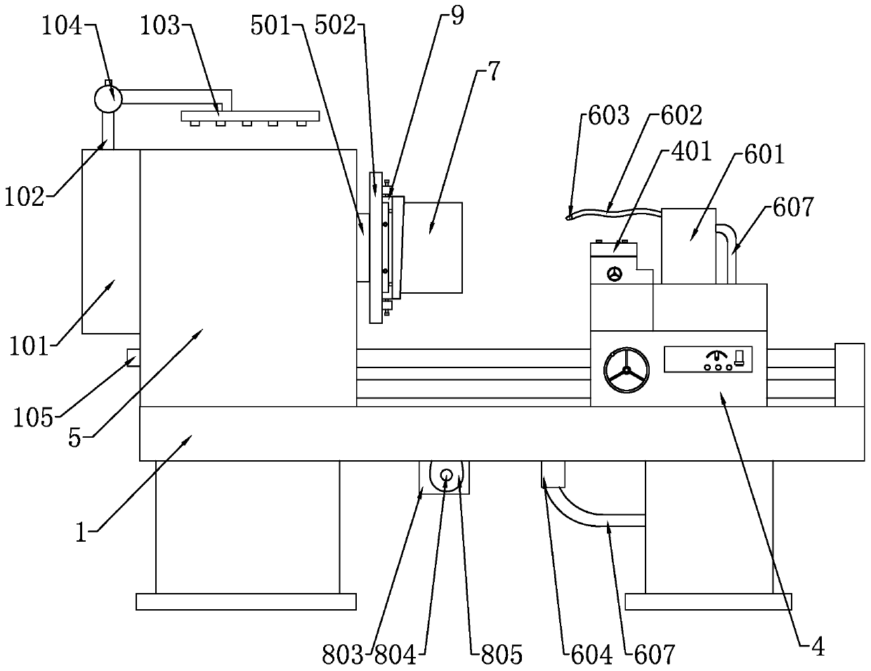
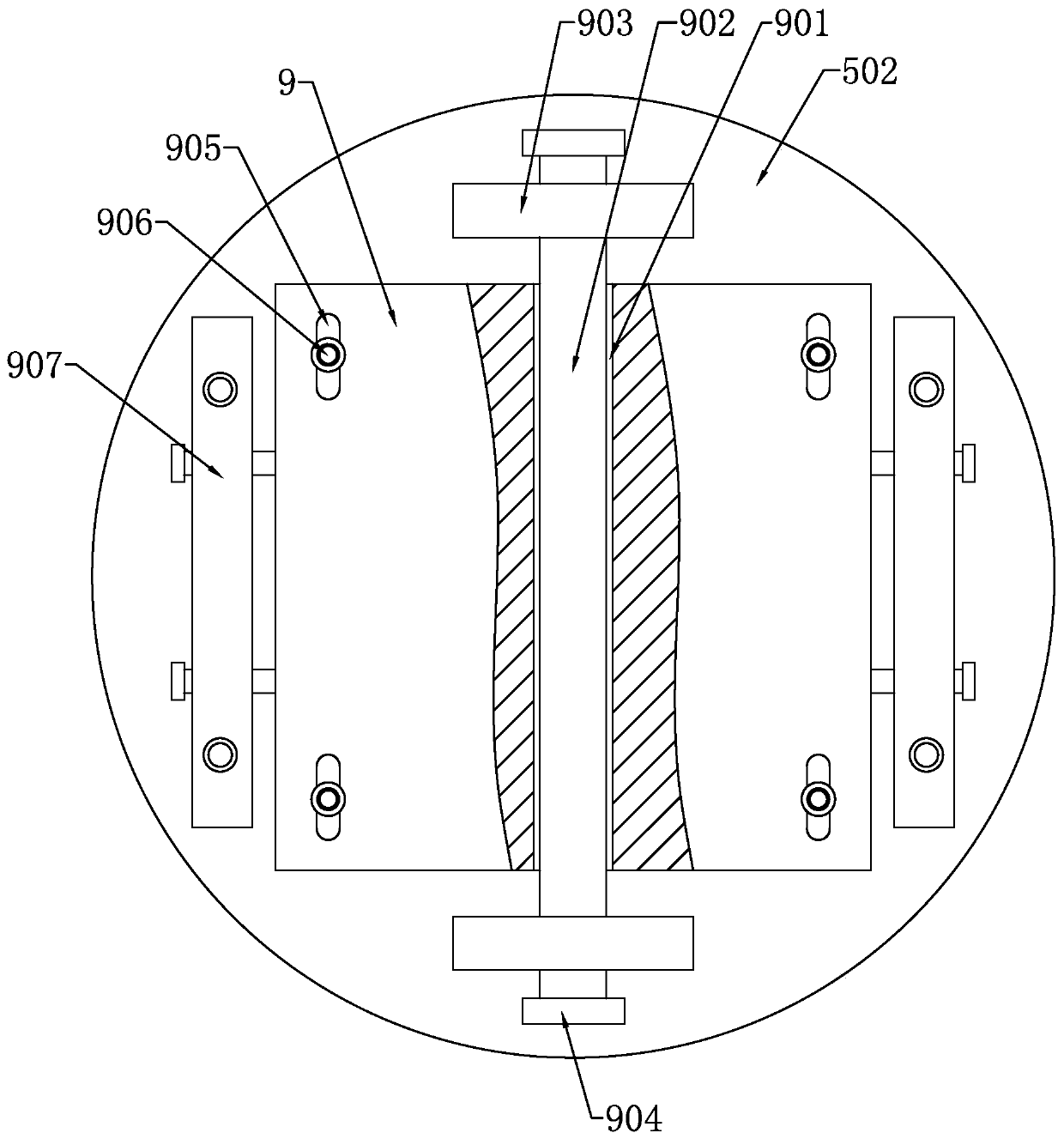
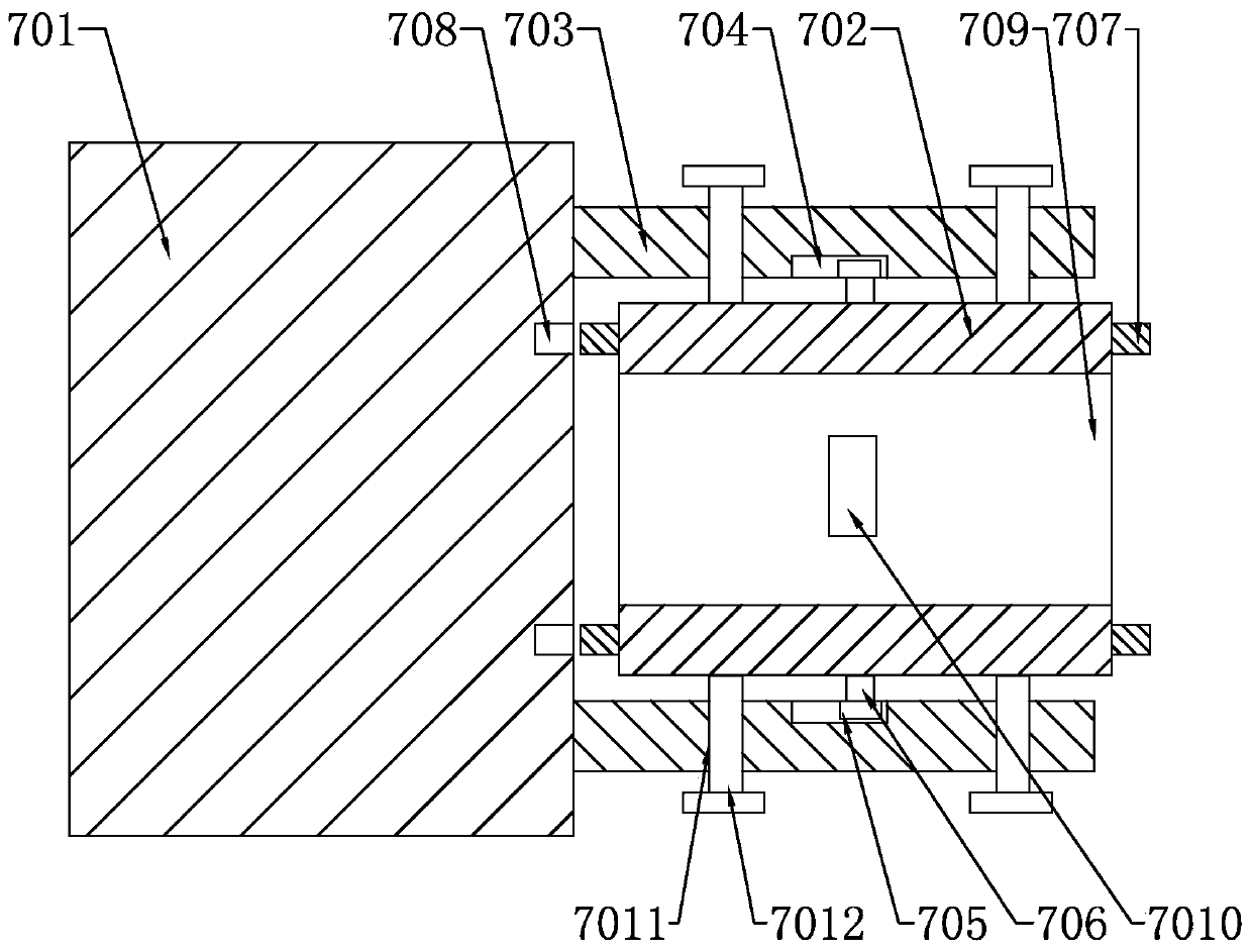
[0044] Such as Figure 1-Figure 9 As shown, the present invention discloses a lathe for processing the inner bevel of the valve seat, comprising a frame 1, a spindle box 5 arranged on the frame 1, the output end of the spindle box 5 is provided with a rotating shaft 501, and the rotating shaft 501 is provided with a clamping device 7 for clamping a workpiece. In a specific embodiment of the present invention: between the rotating shaft 501 and the clamping device 7,...


PUM


Abstract

The invention relates to a lathe for machining an inner slope of a valve seat. The lathe comprises a frame, wherein a spindle box is arranged on the frame, a rotating shaft is arranged at the output end of the spindle box, a clamping device used for clamping a workpiece is arranged on the rotating shaft, and a tilting device used for enabling the clamping device to tilt relative to the rotating shaft and an adjusting device used for enabling the clamping device to shift in the radial direction of the rotating shaft are arranged between the rotating shaft and the clamping device. Compared withthe prior art, by means of the structure, an existing lathe can obtain the valve seat of which an inner hole is inclined and has a certain offset.

Description

technical field [0001] The invention relates to the technical field of valve seat processing, in particular to a lathe used for processing an inner inclined surface of a valve seat and a use method thereof. Background technique [0002] The valve seat is a detachable surface part in the valve, which is used to support the fully closed position of the valve core and constitute a sealing pair. The valve seat can be processed by a lathe. Some valve seats have a sloped inner hole, and the axis of the inner hole and the axis of the valve seat have a certain offset. Processing, when processing a workpiece that needs to be turned at both ends, it needs to be clamped twice, which affects the work efficiency and easily causes the deviation of the coaxiality of the two ends of the workpiece, which cannot meet the requirements of use. The existing lathe tool holder is adjusting The height is achieved by adding or reducing gaskets at the bottom of the tool holder. This method requires ...

Claims


Application Information

Patent Timeline
IPC IPC(8): B23Q3/12B23B31/12B23B21/00B23Q5/28B23B5/00B23Q11/10B23Q11/12B23Q11/00
CPCB23B5/00B23B31/12B23Q1/25B23Q3/12B23Q5/28B23Q11/00B23Q11/10B23Q11/126
Inventor 徐锡平
Owner 浙江诚昌机械配件有限公司
Learn More