Numerical control cut-off machine
A technology of cutting machine and main frame, applied in sawing equipment, mechanical equipment, sugarcane machining and other directions, can solve problems such as high labor intensity
- Summary
- Abstract
- Description
- Claims
- Application Information
AI Technical Summary
Problems solved by technology
Method used
Image
Examples
Embodiment 1
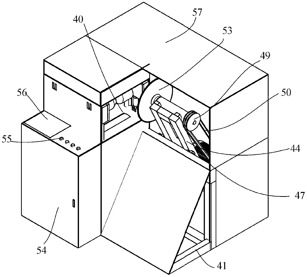
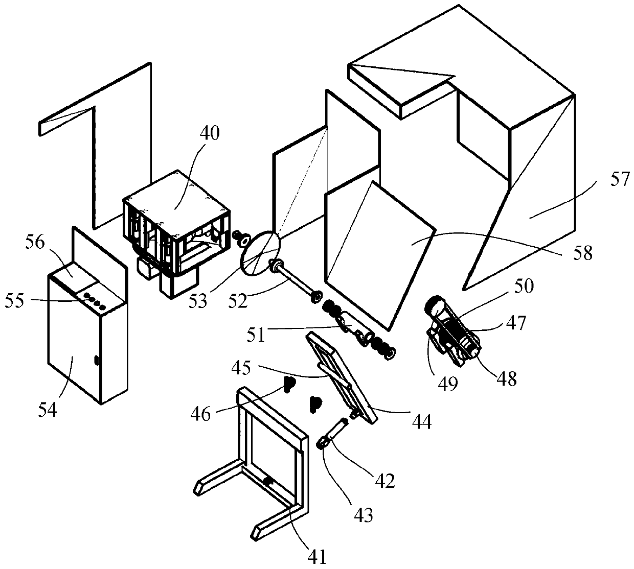
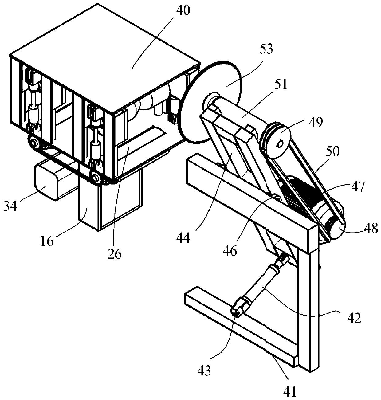
[0034] Such as Figure 1 to Figure 4 As shown, a CNC cutting machine in this embodiment includes a main frame 41, a main cylinder 42, a swing bracket 44, a drive motor 47, a high-speed cylinder 51, a saw shaft 52, a saw blade 53, and a CNC sectional conveyor 40; The middle part of the swing support 44 is rotatably connected to the upper edge of the main frame 41, the cylinder end of the main cylinder 42 is hinged on the lower edge of the main frame 41, and the telescopic rod end of the main cylinder 42 is hinged on the lower edge of the swing support 44. The upper edge is fixed with a high-speed cylinder 51, and the high-speed cylinder 51 is rotationally connected with a saw shaft 52. The drive motor 47 is fixed on the lower edge of the swing bracket 44, and the output shaft of the drive motor 47 is connected to one end of the saw shaft 52. The saw shaft 52 The other end of the saw blade 53 is fixed, and the saw blade 53 is arranged on the side of the material outlet of the nu...
Embodiment 2
[0040] Such as Figure 1 to Figure 4 As shown, a CNC cutting machine in this embodiment includes all the technical features in Embodiment 1, in addition, it also includes a swing shaft 45 and a swing bearing seat 46, and the swing shaft 45 is fixed in the middle of the swing bracket 44 , the two ends of the swing shaft 45 are respectively rotatably connected in the swing bearing seat 46, and the swing bearing seat 46 at the two ends of the swing shaft 45 is fixed on the upper edge of the main frame 41; it also includes a driving pulley 48, a driven pulley 49 and a transmission belt 50, Driving pulley 48 is fixed on the output shaft of driving motor 47, and driven pulley 49 is fixed on saw shaft 52 away from an end of saw blade 53, and is connected by transmission belt 50 between driving pulley 48 and driven pulley 49; Box 54, control button 55, display 56, casing 57 and inclined baffle 58; casing 57 cover is arranged on the outer peripheral side of main frame 41, saw blade 53 ...
Embodiment 3
[0044] Such as Figure 5 to Figure 8 As shown, a numerically controlled cutting machine in the present embodiment, the numerically controlled sectional conveyor 40 includes an upper fixed plate 17, a lower fixed plate 18, an upper fixed frame 39, a first cylinder 19, a slider fixed bracket 22, an upper pressure wheel 23, the lower pressure wheel 29, the servo motor 34 and the segment sensor 16; the upper fixed plate 17 is arranged at intervals directly above the lower fixed plate 18, and the two edges of the upper fixed plate 17 and the lower fixed plate 18 are respectively passed through the four upper The fixed frame 39 is connected, two rectangular openings 26 are provided on the lower fixed plate 18, the length direction of the rectangular opening 26 is perpendicular to the plane where the four upper fixed frames 39 are located, and an upper pressure wheel 23 is arranged directly above each rectangular opening 26 , the two ends of each upper pressure wheel 23 are respectiv...
PUM
 Abstract
Description
Claims
Application Information
 - R&D
- Intellectual Property
- Life Sciences
- Materials
- Tech Scout
- Unparalleled Data Quality
- Higher Quality Content
- 60% Fewer Hallucinations
Browse by: Latest US Patents, China's latest patents, Technical Efficacy Thesaurus, Application Domain, Technology Topic, Popular Technical Reports.
© 2025 PatSnap. All rights reserved.Legal|Privacy policy|Modern Slavery Act Transparency Statement|Sitemap|About US| Contact US: help@patsnap.com


