Offshore oil storage tank
A technology for offshore petroleum and storage tanks, applied in the petroleum field, can solve the problems of low alloy steel corrosion and rust, frequent maintenance, and affecting the use of storage tanks, and achieve the effects of preventing electrochemical corrosion, avoiding excessive rotation, and preventing rusting
- Summary
- Abstract
- Description
- Claims
- Application Information
AI Technical Summary
Problems solved by technology
Method used
Image
Examples
Embodiment 1
[0025] Such as Figure 1-Figure 6 Shown:
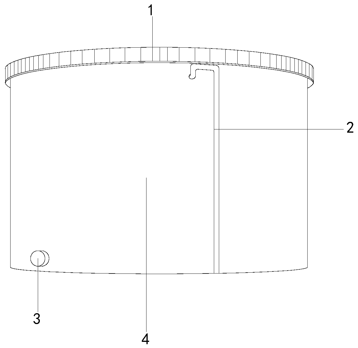
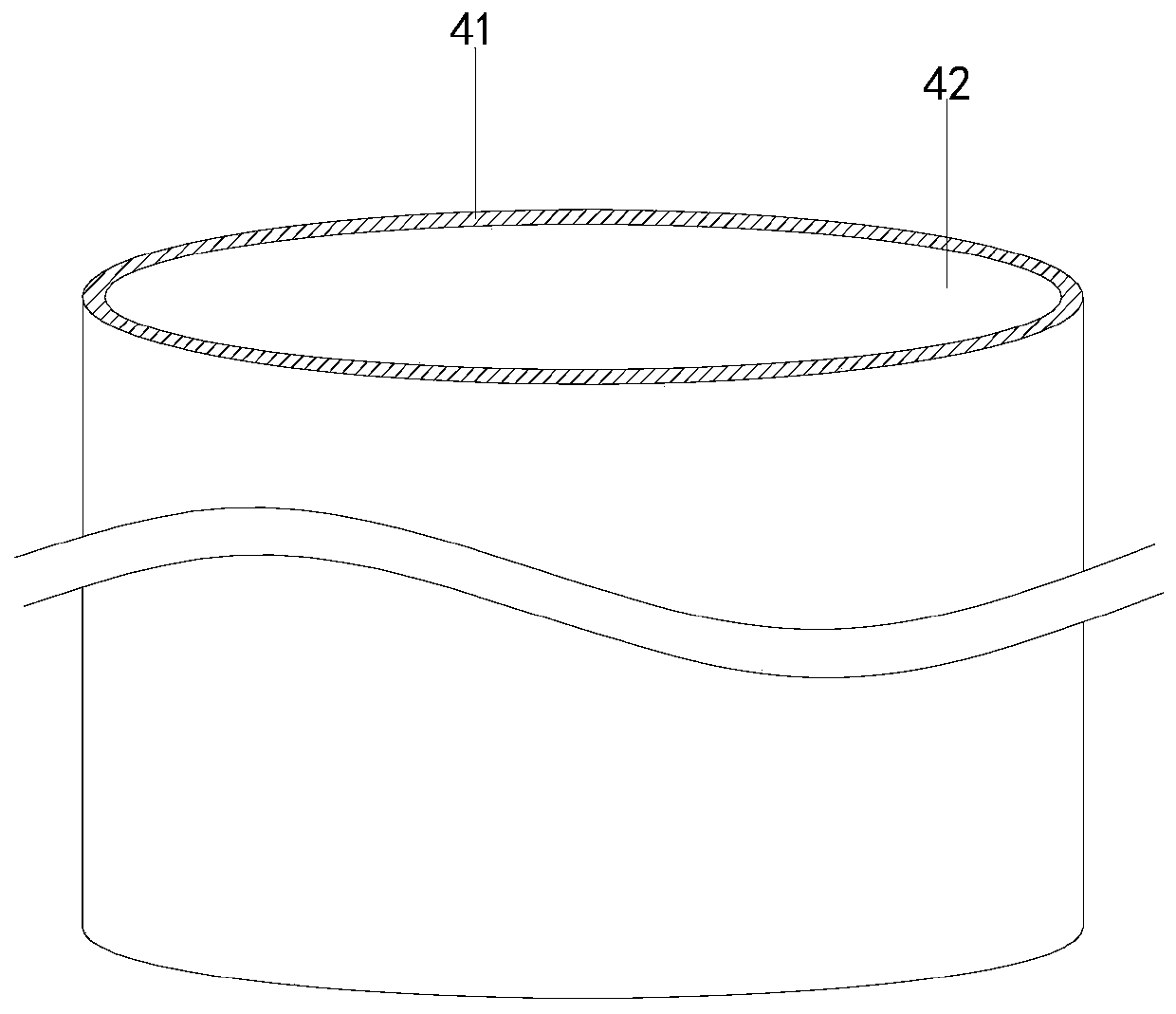
[0026] The present invention is an offshore oil storage tank, the structure of which includes a guardrail 1, an oil suction pipeline 2, an oil outlet pipe 3, and a storage tank 4. The oil suction pipeline 2 is embedded and installed on the side of the storage tank 4. The storage tank 4 is an integrated structure, the guardrail 1 is welded on the upper end of the storage tank 4, the storage tank 4 is provided with a protective mechanism 41 and a storage tank 42, and the protection mechanism 41 is attached to the outside of the storage tank 42. The upper end of the protection mechanism 41 is welded on the outside of the guardrail 1, and the protection mechanism 41 is in a ring structure, and is located on the same central axis as the storage tank 42, so that the storage tank 42 is sealed inside.
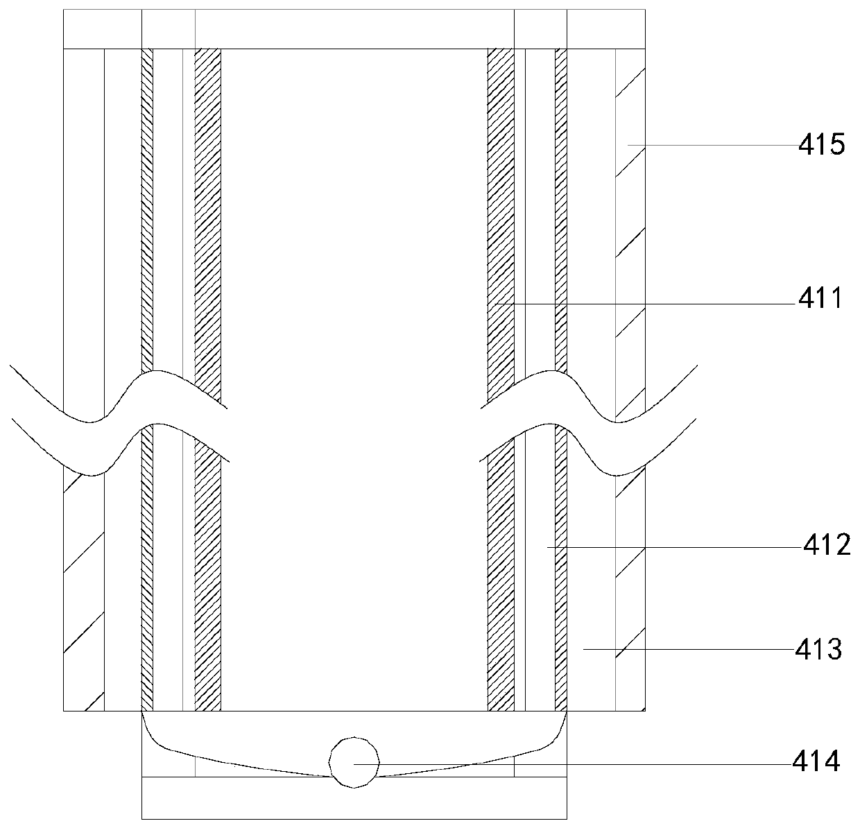
[0027] Wherein, the protective mechanism 41 is provided with a protective layer 411, a collecting tank 412, a sliding mechanism 413, a colle...
Embodiment 2
[0034] Such as Figure 7-Figure 8 Shown:
[0035] Wherein, the cleaning mechanism 415 is composed of a cleaning block c1, a threaded rod c2, a fan c3, a rotating rod c4, and a connection line c5. The connection line c5 is embedded in the upper end of the cleaning block c1, and the threaded rod c2 and the cleaning block c1 is threaded, the rotating rod c4 and the fan c3 are located on the same center line, the lower end of the connecting line c5 is embedded in the rotating rod c4, the cleaning block c1 is attached to the outside of the sliding mechanism 413, and the threaded rod c2 Shaft wheels are installed at both ends, so that the threaded rod c2 can be rotated, and the threaded rod c2 is prevented from rotating too fast.
[0036]Wherein, the cleaning block c1 is provided with a cleaning groove c11, a rotating blade c12, and a fixed block c13, the rotating blade c12 is installed on the right side of the fixing block c13, the cleaning groove c11 and the fixing block c13 are ...
PUM
 Abstract
Description
Claims
Application Information
 - R&D
- Intellectual Property
- Life Sciences
- Materials
- Tech Scout
- Unparalleled Data Quality
- Higher Quality Content
- 60% Fewer Hallucinations
Browse by: Latest US Patents, China's latest patents, Technical Efficacy Thesaurus, Application Domain, Technology Topic, Popular Technical Reports.
© 2025 PatSnap. All rights reserved.Legal|Privacy policy|Modern Slavery Act Transparency Statement|Sitemap|About US| Contact US: help@patsnap.com


