Belt tearing opening shaping structure and belt conveyor

A tearing hole and belt technology, which is applied in the field of belt tearing shaping structure and belt conveyor, can solve problems such as economic loss, uncontrolled tearing range, and insufficient technology, so as to reduce economic loss and avoid tearing Effect

Active Publication Date: 2020-07-17
SHENHUA TIANJIN COAL TERMINAL
View PDF6 Cites 0 Cited by
  • Summary
  • Abstract
  • Description
  • Claims
  • Application Information

AI Technical Summary

Problems solved by technology

However, due to the imperfection of the technology, in practical applications, there will be situations where the belt has been torn but the tear detection device cannot detect it
For example, after the belt is scratched, the material on the belt will not leak from the tear opening to the bottom of the tear opening or get stuck in the middle of the tear opening, causing the tear detection device under the belt, such as a drawstring detection device, weighing The sensory detection device cannot detect the tearing fault, so that sometimes the tearing fault cannot be detected in time, so that the tearing range is not controlled, and finally the staff spends a longer time repairing the belt conveyor, which also causes greater damage. economic loss

Method used


Image

  • Belt tearing opening shaping structure and belt conveyor
  • Belt tearing opening shaping structure and belt conveyor
  • Belt tearing opening shaping structure and belt conveyor

Examples


Embodiment Construction

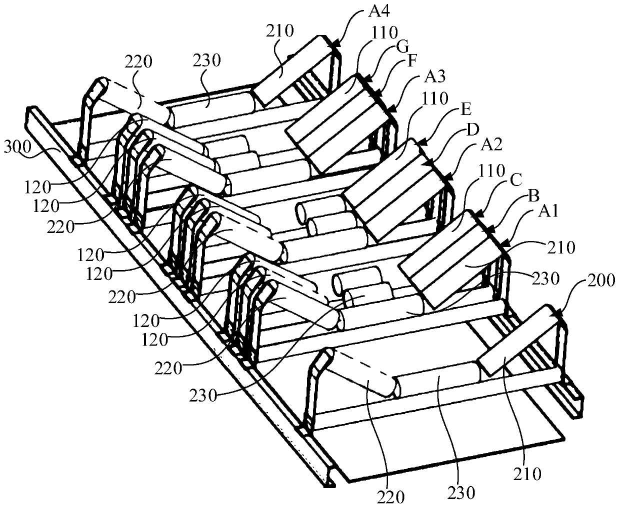
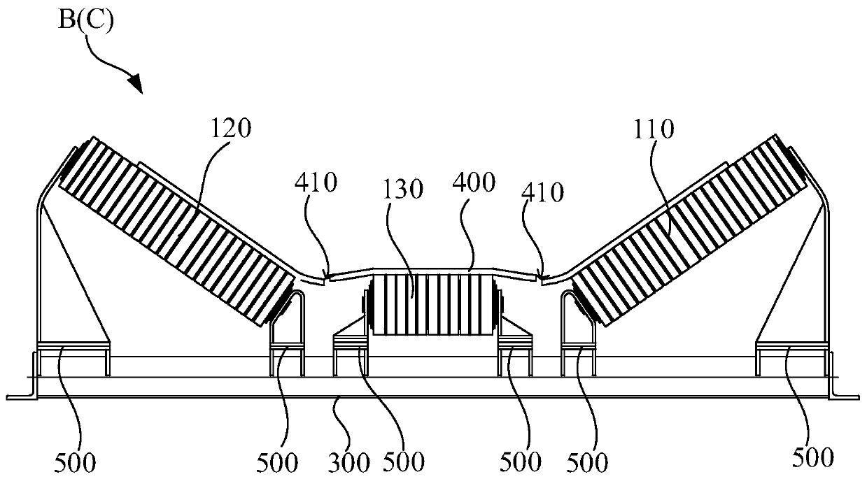
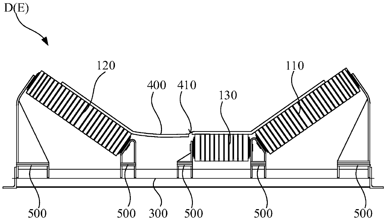
[0033] In order to make the above-mentioned objects, features and advantages of the present invention more obvious and understandable, the specific embodiments of the present invention will be described in detail below with reference to the accompanying drawings. In the following description, many specific details are explained in order to fully understand the present invention. However, the present invention can be implemented in many other ways different from those described herein, and those skilled in the art can make similar improvements without departing from the connotation of the present invention. Therefore, the present invention is not limited by the specific embodiments disclosed below.

[0034] In the description of the present invention, it should be understood that the terms "center", "longitudinal", "transverse", "length", "width", "thickness", "upper", "lower", "front", " "Back", "Left", "Right", "Vertical", "Horizontal", "Top", "Bottom", "Inner", "Outer", "Clockw...


PUM


Abstract

The invention relates to a belt tearing opening shaping structure and a belt conveyor. The belt tearing opening shaping structure comprises a shaping carrier roller set, a groove type carrier roller set and a carrier roller frame. The shaping carrier roller set comprises a middle shaping carrier roller, a first side shaping carrier roller and a second side shaping carrier roller, and the first side shaping carrier roller and the second side shaping carrier roller are arranged at the two ends of the middle shaping carrier roller. The first side shaping carrier roller and the second side shapingcarrier roller are obliquely arranged and are inclined towards the middle shaping carrier roller. The middle shaping carrier roller and the first side shaping carrier roller are arranged at an interval, or the middle shaping carrier roller and the second side shaping carrier roller are arranged at an interval. The shaping carrier roller set is arranged in parallel to the groove type carrier roller set in the length direction, and the groove type carrier roller set comprises a middle carrier roller. The groove type carrier roller set and the shaping carrier roller set are both arranged on thecarrier roller frame, and the distance between the middle shaping carrier roller and the bottom of the carrier roller frame is larger than the distance between the middle carrier roller and the bottomof the carrier roller frame. According to the mechanism, it is guaranteed that a tearing opening is detected by a tearing detecting device, a worker can repair the belt conveyor in time, and economiclosses are reduced.

Description

Technical field [0001] The invention relates to the technical field of belt conveyor tear prevention, in particular to a belt tear opening shaping structure and a belt conveyor. Background technique [0002] At present, belt conveyors are widely used in the field of bulk cargo transportation in ports and mining areas. The belt type used by the belt conveyor is mainly a steel cord conveyor belt. This conveyor belt has extremely high strength and good grooving performance, and is suitable for high-speed, large-load, and long-distance continuous transportation. But in the process of transporting materials, impurities from the materials or sharp objects falling from the transportation equipment can easily scratch the bearing surface of the belt. After the belt is scratched, it can be detected by a tear detection device such as a mechanical pull-rope detection device, an X-ray camera device, and a load cell detection device. However, due to insufficient technology, in practical appl...

Claims


Application Information

Patent Timeline
Patent Type & Authority Applications(China)
IPC IPC(8): B65G39/12
CPCB65G39/125
Inventor 朱相福
Owner SHENHUA TIANJIN COAL TERMINAL
Why Eureka
Try Eureka