Bobbin device for textile machine

A technology of textile machinery and bobbins, applied in the field of bobbin devices, which can solve problems such as unwinding forming, affecting yarn quality, poor yarn winding, etc., to avoid breakage, improve winding quality, and simple and convenient installation and disassembly Effect

Active Publication Date: 2020-07-17
嘉兴市金进纺织股份有限公司
View PDF6 Cites 9 Cited by
  • Summary
  • Abstract
  • Description
  • Claims
  • Application Information

AI Technical Summary

Problems solved by technology

[0005] In the process of textile processing, the yarn processed from textile fibers needs to be wound on the bobbin. When the yarn is wound, the bobbin rotates continuously and moves along the axial direction so that the yarn is evenly wound on the outer wall of the bobbin. ; but the existing yarn bobbin structure is a fixed bobbin structure, and the crossbow has the function of elastic adjustment. During the yarn winding process, various problems such as the unwinding speed, the winding speed and the thickness of the yarn itself may appear. When the yarn is poorly wound on the bobbin, it is too loose to be wound into shape, or the yarn is too tensioned to cause the yarn to break and other problems, which affect the quality of the yarn

Method used


Image

  • Bobbin device for textile machine
  • Bobbin device for textile machine
  • Bobbin device for textile machine

Examples


Embodiment 1

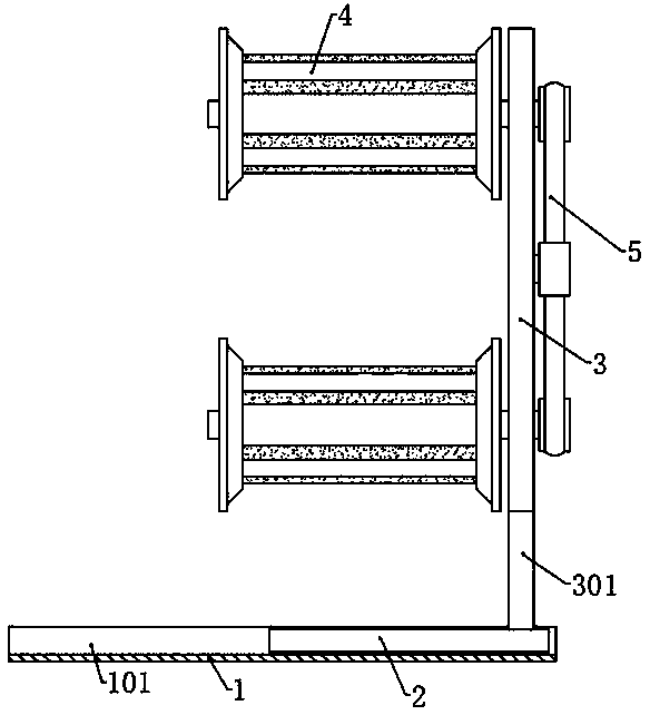
[0030] Please refer to the accompanying drawings, the present invention provides a technical solution: a yarn bobbin device for textile machinery, including a base 1, a chute 101 is provided in the middle of the top surface of the base 1, and a moving seat 2 is slidably connected to the chute 101, The top surface of the moving seat 2 is symmetrically fixed with a fixed rod 301, and the top of the fixed rod 301 is jointly fixed with a fixed plate 3, and the left side of the fixed plate 3 is provided with four bobbin assemblies 4 in a rectangular array, and the right side is provided with a drive component 5;

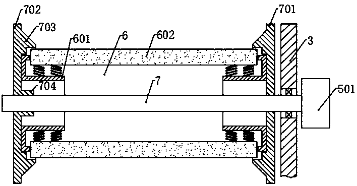
[0031] Yarn bobbin assembly 4 comprises the rotating shaft 7 that is vertical and rotationally connected with fixed bar 301, and the left section of rotating shaft 7 is provided with movable baffle 702, and the right side of movable baffle 702 is provided with fixed baffle 701, and the rotating shaft The right end on 7 passes through the fixed plate 3 and is corresponding...

Embodiment 2

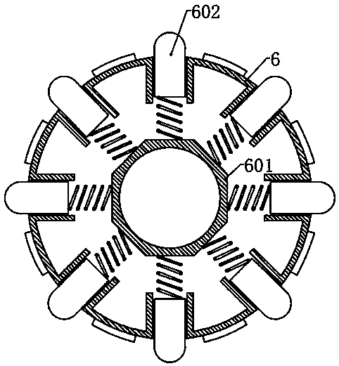
[0038] The structure of this embodiment is basically the same as that of Embodiment 1, the difference is that a circular yarn guiding platform 703 is symmetrically fixed on the inner side of the fixed baffle 701 and the moving baffle 702, and the outer circle side of the yarn guiding platform 703 The wall is inclined to the direction of the rotating shaft 7, and the center of the inner surface of the yarn guide table 703 is provided with a circular receiving groove, and the center of the circular side wall of the receiving groove is provided with a mounting groove, and the two ends of the cylinder body 6 are respectively located In the installation groove, the two ends of the telescopic block 602 are respectively located in the accommodation groove; when the cylinder 6 is installed, the two ends of the cylinder 6 are respectively located in the installation grooves on both sides, so that the position of the cylinder 6 is limited so that it is in line with the rotation The shaft...

Embodiment 3

[0042] The structure of this embodiment is basically the same as that of Embodiment 2, the difference being that a spring groove 302 is provided at the position corresponding to the tension wheel 502 on the fixed plate 3, and a moving block 503 is slidably connected to the spring groove 302, and the outer side of the moving block 503 A spring is provided between the end and the outer end of the spring groove 302, and the tensioning wheel 502 is rotationally connected with the moving block 503. Through the action of the spring and the moving block 503, the tensioning wheel 502 can always tension the transmission belt, improving the stability of the transmission. sex.

[0043] The side wall of the chute 101 is provided with a limit groove along the length direction, and a limit bar is fixed on the outer surface of the vertical rod, and the limit bar is slidably connected in the limit groove to prevent the movable seat 2 from accidentally breaking away from the base 1.


PUM


Abstract

The invention discloses a bobbin device for a textile machine, and belongs to the technical field of textile processing. The bobbin device comprises a base, a movable seat is slidably connected to thebase through a sliding groove, a fixed plate is fixed to the top surface of the movable seat, a bobbin assembly is arranged on the left side of the fixed plate, and a driving assembly is arranged onthe right side of the fixed plate. According to the device, a bobbin in the bobbin assembly is rotated through the driving assembly, and meanwhile, the movable seat drives the fixed plate and the bobbin assembly to move back and forth, so that yarn is wound on the bobbin, and winding is completed. The yarn is tensioned during winding under the action of a telescopic block and a spring, the problemthat the yarn is too loose and cannot be shaped during winding is avoided, or when the yarn is too tensioned during winding, the telescopic block is compressed to reduce the tensioning degree of theyarn, and yarn breakage is avoided; and a movable baffle is screwed off, a new bobbin is installed after the bobbin is taken down, the movable baffle is screwed on, the bobbin is clamped and fixed through the movable baffle and a fixed baffle, and the bobbin is simple and convenient to mount and disassemble.

Description

technical field [0001] The invention relates to the technical field of textile processing, in particular to a yarn bobbin device for textile machinery. Background technique [0002] The original meaning of textile is taken from the general term of spinning and weaving, but with the continuous development and improvement of the textile knowledge system and subject system, especially after the emergence of non-woven textile materials and three-dimensional composite weaving technologies, the current textile is not only a traditional Hand spinning and weaving also include clothing, industrial and decorative textiles produced by non-woven technology, modern three-dimensional weaving technology, and modern electrostatic nano-netting technology. Therefore, modern textile refers to a kind of fiber or fiber collection. Solid multi-scale structure processing technology. [0003] Ancient Chinese textile and printing and dyeing technology has a very long history. As early as the primit...

Claims


Application Information

Patent Timeline
Patent Type & Authority Applications(China)
IPC IPC(8): B65H54/44B65H54/20B65H54/72B65H54/74B65H75/14B65H75/22B65H75/24
CPCB65H54/20B65H54/44B65H54/72B65H54/74B65H75/148B65H75/22B65H75/245B65H2701/31
Inventor 胡达
Owner 嘉兴市金进纺织股份有限公司
Why Eureka
Try Eureka