Rubber hose braid processing system and processing technology

A processing system and rubber hose technology, which is applied in the rubber hose braided layer processing system and processing technology field, can solve the problem of reducing the production and processing efficiency of rubber hoses, the cumbersome process of rubber hose braided layer, and the cumbersome process of manual winding and braiding, etc. problems, to achieve the effect of shortening the production and processing cycle, improving production efficiency, and avoiding knotting and jamming

Active Publication Date: 2020-07-17
卓凡液压科技有限公司
10 Cites 0 Cited by

AI-Extracted Technical Summary

Problems solved by technology

[0004] (1) When the braided layer of the rubber hose is processed manually, it is usually necessary to manually wind the inner rubber layer of the rubber hose to the tube roller, and then wind the braided rope outside the inner rubber layer, and the braided rope is wound. Finally, the outer rubber layer of the rubber hose is manually wrapped on the tube roller. The manual winding and weaving process is cumbersome, and the braided rope is easy to loose during the manual winding process, which makes the processing quality of the rubber hose poor;
[0005] (2) When the existin...

Method used

Described tension mechanism 55 comprises rubber wheel 551, two mounts 552, two extruding rods 553, two extruding wheels 554, adjusting screw rod 555 and compression spring 556, and rubber wheel 551 is installed on rope by bearing The middle part of the left end of the frame 54, the lower end of the rubber wheel 551 is equipped with a mount 552 symmetrically before and after, the upper end of the mount 552 is equipped with an extruding rod 553 through a pin shaft, the upper end of the extruding rod 553 is equipped with an extruding wheel 554 through a bearing, and the middle part of the extruding rod 553 An adjusting screw 555 is installed through thread fit, and the middle part of the adjusting screw 555 is covered with a compression spring 556. During specific work, the braided rope is manually placed on the right end of the rubber wheel 551, and the braid...

Abstract

The invention relates to a rubber hose braid processing system and a processing technology. The rubber hose braid processing system comprises a workbench, two side plates, a driving device, a rubber winding device and a winding device, wherein the side plates are bilaterally and symmetrically installed at an upper end of the workbench, the driving device is installed on the outer sides of the sideplates, the rubber winding device is installed at the right ends of the inner sides of the side plates, and the winding device is arranged on a rear side of the rubber winding device. The rubber hosebraid processing system provided by the invention can solve the problems that the manual winding and braiding process is tedious due to a fact that an inner rubber layer is firstly wound on a pipe making roller, then a braided rope is wound on the outer side of the inner rubber layer, and then an outer rubber layer is wound on rubber when a rubber hose braid is manually processed, the braided rope is easy to loosen, the process for manufacturing the rubber hose braid is tedious due to the fact that the inner rubber layer of the rubber hose is firstly wound, and then the braided rope is woundon the outer side of the inner rubber layer, and then the outer glue layer is wound on the rubber when during the processing of the existing rubber hose processing equipment; and the manufacturing andprocessing efficiency of the rubber hose is reduced.

Technology Topic

Image

  • Rubber hose braid processing system and processing technology
  • Rubber hose braid processing system and processing technology
  • Rubber hose braid processing system and processing technology

Examples

  • Experimental program(1)

Example Embodiment

[0038] In order to make the technical means, creative features, objectives and effects of the present invention easy to understand, the following is combined Figure 1 to Figure 9 , To further explain the present invention.
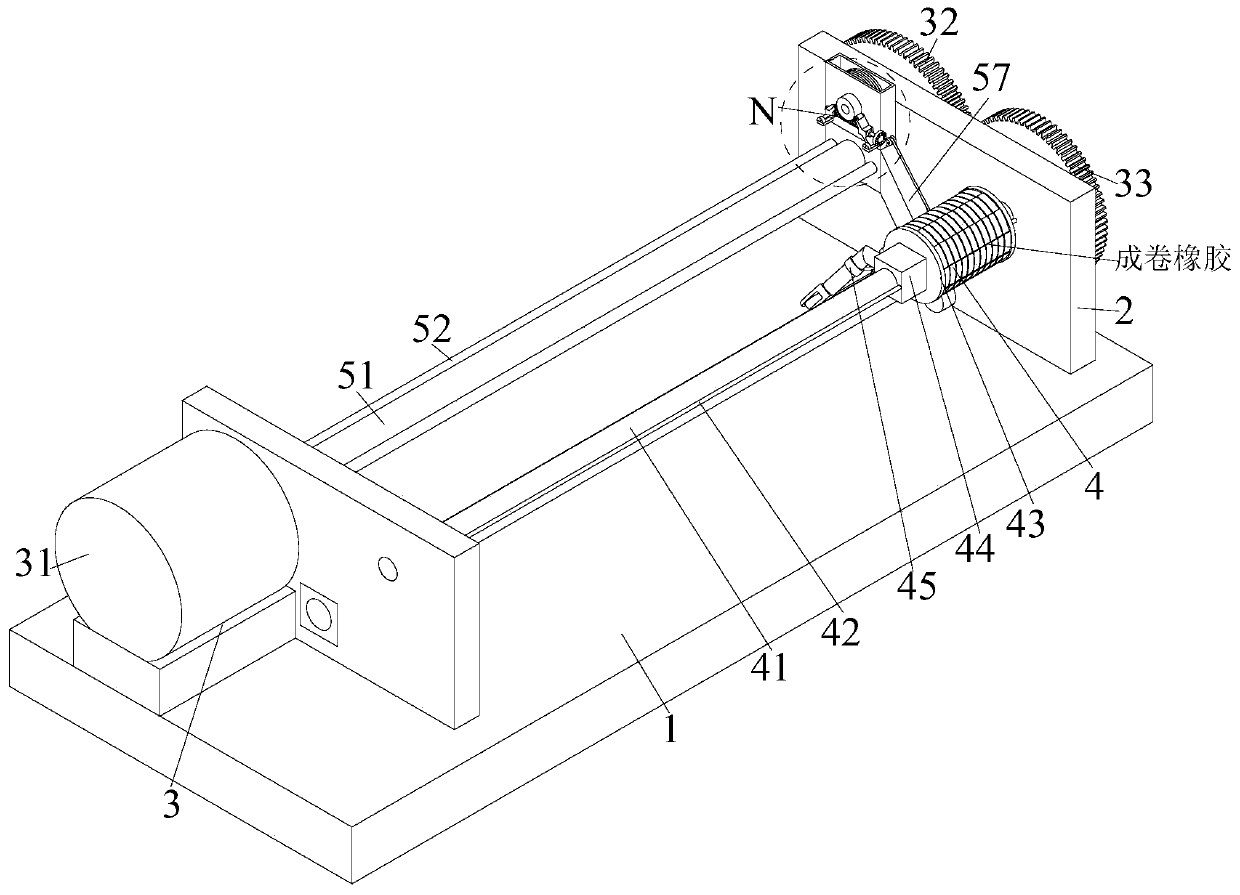
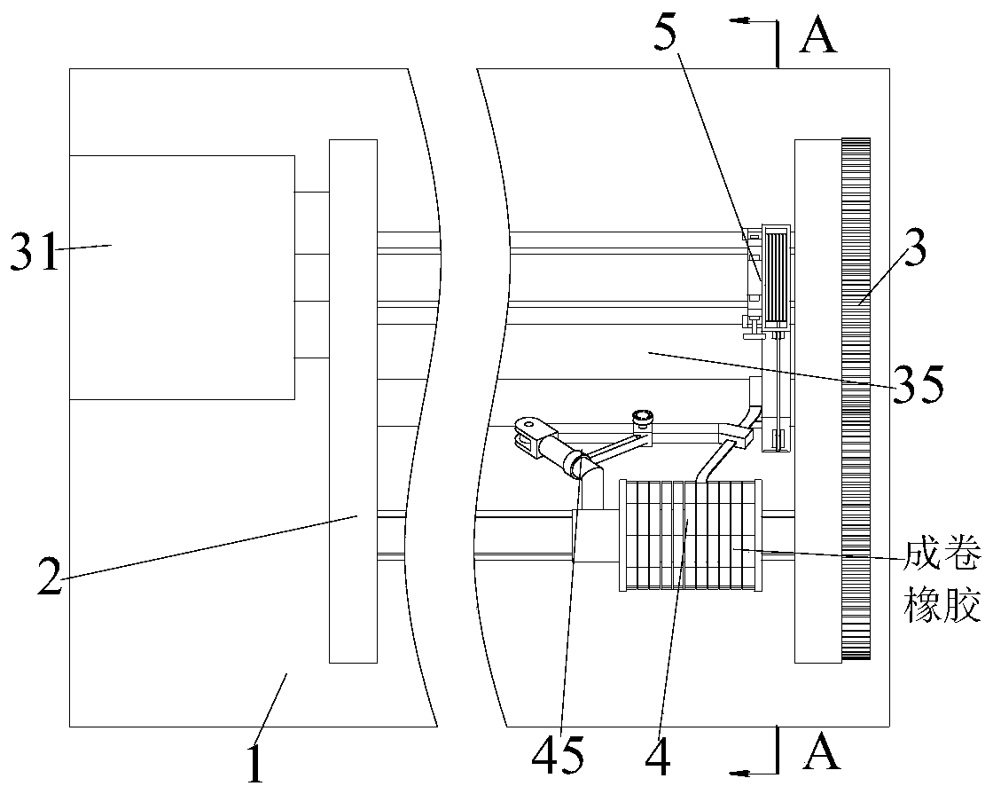
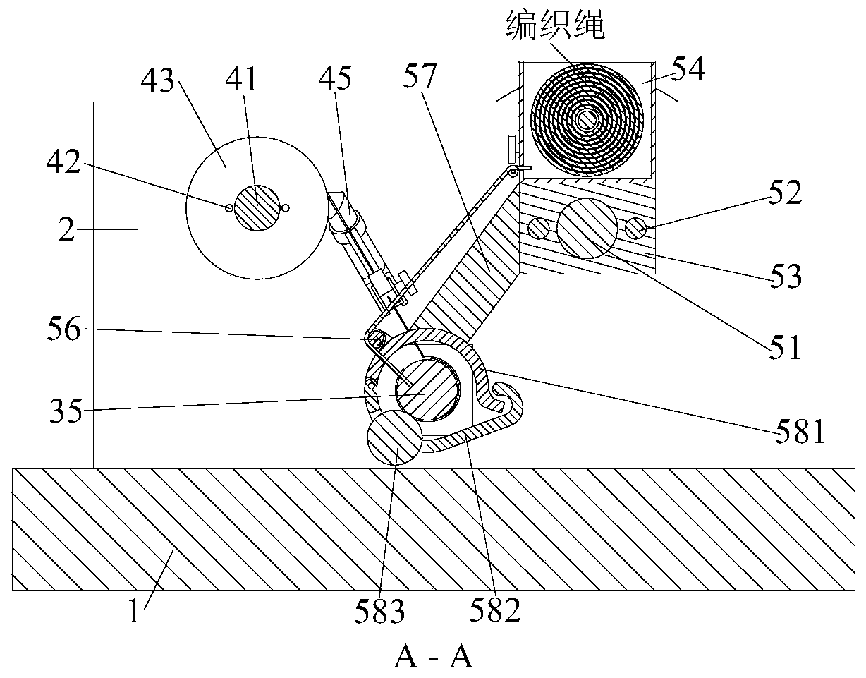
[0039] A rubber hose braid processing system includes a workbench 1, two side plates 2, a driving device 3, a rubber winding device 4, and a winding device 5. The upper end of the workbench 1 is provided with side plates 2 symmetrically. A driving device 3 is installed on the outside of the board 2, a glue winding device 4 is installed on the right end of the inner side of the side board 2, and a winding device 5 is arranged on the rear side of the glue winding device 4;
[0040] The driving device 3 includes a rotating motor 31, a driving gear 32, a driven gear 33, a tube-making gear 34, and a tube-making roller 35. The rotating motor 31 is installed on the left side of the upper end of the table 1 through a motor mounting plate, and the rotating motor 31 outputs The winding device 5 is connected to the winding device 5. The right end of the winding device 5 is equipped with a drive gear 32. The front end of the drive gear 32 is meshed with a driven gear 33. The driven gear 33 is installed at the right end of the glue winding device 4, and the lower end of the drive gear 32 is meshed with a tube The gear 34 is equipped with a pipe-making roller 35 at the left end of the pipe-making gear 34. The pipe-making roller 35 is installed between the side plates 2 through bearings. During specific work, the rolled rubber is manually placed on the rubber winding device 4. And through the rotation of the rotating motor 31, the drive gear 32 drives the pipe making gear 34 to rotate, so that the rubber is wound on the pipe making roller 35, and the driven gear 33 is driven to rotate through the drive gear 32, so that the rubber winding device 4 removes the rubber from Winding from right to left on the tube-making roller 35, and during the glue winding process, the drive gear 32 is driven to rotate by the rotating motor 31, so that the winding device 5 winds the outside of the rubber after winding, so that the winding device 5 Weave the braid of the rubber hose from right to left.
[0041] The glue wrapping device 4 includes a feeding screw 41, two guide rods 42, a rubber seat 43, a mounting block 44, and an angle adjustment mechanism 45. The feeding screw 41 is mounted on the inner side of the side plate 2 through a bearing. The front and rear ends of the rod 41 are symmetrically provided with a guide rod 42. The guide rod 42 serves as a limit guide. The feeding screw 41 is equipped with a rubber seat 43 through a threaded fit, and a mounting block 44 is installed at the left end of the rubber seat 43 , And the rubber seat 43 and the mounting block 44 are sleeved on the guide rod 42 through a sliding fit. The rear end of the mounting block 44 is equipped with an angle adjustment mechanism 45. During specific work, the rolled rubber is manually placed on the rubber On the seat 43, the angle adjusting mechanism 45 adjusts the glue wrapping angle on the pipe-making roller 35. After the angle adjustment is completed, the driving gear 32 is driven to rotate by the rotating motor 31, so that the driven gear 33 drives the feeding screw 41 to rotate , So that the rubber seat 43 and the mounting block 44 drive the angle adjusting mechanism 45 to move to the left, so that the angle adjusting mechanism 45 winds the rubber on the rubber seat 43 on the pipe making roller 35 from right to left.
[0042] The angle adjustment mechanism 45 includes a mounting post 451, a support rod 452, a support head 453, a circular sliding sleeve 454, a square sliding sleeve 455, an adjustment rod 456, and a locking bolt 457. The mounting post 451 is mounted on the mounting block 44, The lower end of the column 451 is hinged with a support rod 452, the right end of the support rod 452 is welded with a support head 453, the middle of the mounting column 451 is sleeved with a circular sliding sleeve 454, and the middle of the support rod 452 is sleeved with a square sliding sleeve 455. 454 and the square sliding sleeve 455 are connected by an adjusting rod 456, and the square sliding sleeve 455 is fixed on the support rod 452 by a locking bolt 457. During specific work, the roll of rubber is manually placed on the rubber seat 43 and the rubber One end passes through the support head 453 to fix the rubber on the pipe-making roller 35. After the rubber is fixed, the locking bolt 457 is manually rotated to separate the support rod 452 from the square sliding sleeve 455, so that the circular sliding sleeve 454 and The square sliding sleeve 455 drives the adjustment rod 456 to move, so that the adjustment rod 456 adjusts the angle between the mounting post 451 and the support rod 452 to determine the wrapping angle. After the wrapping angle is determined, the locking bolt 457 is manually rotated in reverse. , So that the square sliding sleeve 455 fixes the adjusting rod 456, thereby fixing the glue wrapping angle.
[0043] The support head 453 is evenly provided with roller columns inside, and the roller columns facilitate the support head 453 to transfer rubber and prevent the rubber from getting stuck in the support head 453.
[0044] The winding device 5 includes a moving screw 51, two guide rods 52, a sliding block 53, a rope frame 54, a tensioning mechanism 55, two steering wheels 56, a connecting rod 57 and a winding mechanism 58, and the moving screw 51 Mounted on the inner side of the side plate 2 by bearings, two guide rods 52 are symmetrically provided at the front and rear ends of the moving screw 51, a sliding block 53 is installed on the moving screw 51 by threaded fitting, and a rope frame 54 is installed on the upper end of the sliding block 53. A tensioning mechanism 55 is installed at the left end of the rope frame 54. A steering wheel 56 is installed at the front end of the rope frame 54. A connecting rod 57 is installed at the lower end of the steering wheel 56. A winding mechanism 58 is installed at the lower end of the connecting rod 57. The winding mechanism 58 is sleeved on the pipe making roller. Outside the column 35, a steering wheel 56 is installed at the upper end of the winding mechanism 58. During specific work, the braided rope is manually placed in the rope frame 54 and one end of the braided rope is passed through the rope frame 54, the steering wheel 56 and the winding mechanism 58 and fixed in On the pipe-making roller 35, the angle adjustment mechanism 45 winds the rubber on the rubber seat 43 from right to left on the pipe-making roller 35. The rotating motor 31 drives the moving screw 51 to rotate, so that the sliding block 53 drives the rope frame. 54 is moved to the left, so that the winding mechanism 58 winds the braided rope from right to left on the outside of the wound rubber, and during the winding process, the braided rope is tightened by the tensioning mechanism 55 to ensure that the braided rope is tightly wound.
[0045] The tensioning mechanism 55 includes a rubber wheel 551, two mounting seats 552, two extrusion rods 553, two extrusion wheels 554, an adjusting screw 555 and a compression spring 556. The rubber wheel 551 is mounted on the left end of the rope frame 54 through a bearing. In the middle, the lower end of the rubber wheel 551 is symmetrically installed with a mounting seat 552. The upper end of the mounting seat 552 is equipped with an extrusion rod 553 through a pin. The upper end of the extrusion rod 553 is equipped with an extrusion wheel 554 through a bearing. The center of the extrusion rod 553 is fitted with threads. The adjustment screw 555 is installed in the middle of the adjustment screw 555, and the compression spring 556 is sleeved in the middle of the adjustment screw 555. When working, the braided rope is manually placed on the right end of the rubber wheel 551. The braided rope is adjusted by manual rotation during the winding process from right to left. The screw 555, so that the extrusion rod 553 drives the extrusion wheel 554 to adhere to the rubber wheel 551 tightly, thereby increasing the friction between the extrusion wheel 554 and the rubber wheel 551, so that the rubber wheel 551 will weave The rope is tightened to ensure that the braided rope is tightly wound.
[0046] The winding mechanism 58 includes a fixed arc plate 581, a rotating arc plate 582, and a pressure roller 583. The fixed arc plate 581 is installed at the lower end of the connecting rod 57 by welding, and the lower end of the fixed arc plate 581 is hinged The curved plate 582 is rotated, and a pressure roller 583 is installed inside the front end of the curved plate 582 through a bearing.
[0047] The fixed arc-shaped plate 581 and the rotating arc-shaped plate 582 are sleeved on the pipe-making roller column 35, and the fixed arc-shaped plate 581 and the rotating arc-shaped plate 582 are clamped and fixed at the rear end.
[0048] In specific work, when winding, the fixed arc plate 581 is located above the tube-making roller column 35, so that the braided rope is fixed and discharged from above, and the arc plate 581 is clamped by rotating the arc plate 582, so that the pressing roller 583 rolls the braided rope after winding to ensure that the braided rope is more tightly wound.
[0049] The rope frame 54 has a rope hole on the lower side of the front end, and a rope hole is opened on the upper end of the fixed arc-shaped plate 581. One end of the braided rope is manually passed through the rope hole on the rope frame 54 and on the fixed arc-shaped plate 581. The threaded hole is used to limit the position of the braided rope that is moved out of the material to avoid knotting when the braided rope is discharged.
[0050] In addition, the present invention also provides a rubber hose braid processing technology, which is mainly completed by the above-mentioned rubber hose braid processing system, and specifically includes the following steps:
[0051] S1. Feeding: manually place the roll of rubber on the rubber seat 43 so that one end of the rubber passes through the support head 453 and is fixed on the pipe-making roller column 35, and the braided rope is manually placed in the rope frame 54 to make a fixed arc The plate 581 and the rotating arc plate 582 are clamped and sleeved on the outside of the pipe making roller 35, so that one end of the braided rope is fixed on the pipe making roller 35;
[0052] S2. Adjust the wrapping angle: After loading, manually rotate the locking bolt 457 to separate the support rod 452 from the square sliding sleeve 455, so that the adjustment rod 456 adjusts the angle between the mounting post 451 and the support rod 452 , After the wrapping angle is determined, manually rotate the locking bolt 457 in the opposite direction to fix the wrapping angle;
[0053] S3. Bottom rubber wrapping: After the wrapping angle is adjusted, the rotating motor 31 rotates to make the feeding screw 41 rotate, so that the rubber seat 43 and the mounting block 44 drive the angle adjustment mechanism 45 to move to the left, thereby making the angle adjustment mechanism 45 Wrap the rubber on the pipe roller 35 from right to left;
[0054] S4. Winding and weaving: In the process of winding the bottom rubber, the rotating motor 31 drives the moving screw 51 to rotate, so that the sliding block 53 drives the rope frame 54 to move to the left, so that the winding mechanism 58 winds the braided rope from right to left. The outer side of the finished rubber, and during the winding process, the braided rope is tightened by the tightening mechanism 55;
[0055] S5. Unloading: After the rubber hose is wound and braided, manually remove the finished rubber hose for centralized collection.
[0056] The above shows and describes the basic principles, main features and advantages of the present invention. Those skilled in the industry should understand that the present invention is not limited by the above embodiments. The above embodiments and the description in the specification only illustrate the principles of the present invention. Without departing from the spirit and scope of the present invention, the present invention will also There are various changes and improvements, and these changes and improvements fall within the scope of the claimed invention. The scope of protection claimed by the present invention is defined by the appended claims and their equivalents.

PUM

no PUM

Description & Claims & Application Information

We can also present the details of the Description, Claims and Application information to help users get a comprehensive understanding of the technical details of the patent, such as background art, summary of invention, brief description of drawings, description of embodiments, and other original content. On the other hand, users can also determine the specific scope of protection of the technology through the list of claims; as well as understand the changes in the life cycle of the technology with the presentation of the patent timeline. Login to view more.

Similar technology patents

Novel high-strength and wear-resistant thermochromic glass milk bottle and preparation process thereof

PendingCN105997524AImprove cutting efficiency and effectShorten the production and processing cycleFeeding-bottlesGlass reforming apparatusChemistryBiotechnology
Owner:DANYANG SHUANGFENG GLASS

Fully-automatic vacuum packing device for drugs

Owner:亳州广源堂中药饮片有限公司

Flight verification auxiliary system based on flat plate

ActiveCN111125037AReduce cumbersome processReduce the chance of infectionFile metadata searchingTransmissionFile transferData synchronization
Owner:BEIJING SKY AVIATION CO LTD

Oil cylinder load test platform

PendingCN111637114AReduce cumbersome processImprove efficiency and test accuracyFluid-pressure actuator testingMeasurement devicesPhysicsElectric machinery
Owner:CHANGZHI QINGHUA MACHINERY FACTORY

Method to separate enriched Z and E types of 3-chloro-2-(4-fluorophenyl)-1-(2-chlorophenyl)propylene

InactiveCN108530263AShorten the production and processing cycleImprove production processing speedOrganic chemistry methodsHalogenated hydrocarbon separation/purificationOrganic solventMixed solution
Owner:SOUTHEAST UNIV

Classification and recommendation of technical efficacy words

  • Shorten the production and processing cycle
  • Reduce cumbersome process

Fully-automatic vacuum packing device for drugs

Owner:亳州广源堂中药饮片有限公司

Novel high-strength and wear-resistant thermochromic glass milk bottle and preparation process thereof

PendingCN105997524AImprove cutting efficiency and effectShorten the production and processing cycleFeeding-bottlesGlass reforming apparatusChemistryBiotechnology
Owner:DANYANG SHUANGFENG GLASS

Method to separate enriched Z and E types of 3-chloro-2-(4-fluorophenyl)-1-(2-chlorophenyl)propylene

InactiveCN108530263AShorten the production and processing cycleImprove production processing speedOrganic chemistry methodsHalogenated hydrocarbon separation/purificationOrganic solventMixed solution
Owner:SOUTHEAST UNIV

Method for preparing hierarchical porous titanium silicalite TS-1

InactiveCN101962195ALower synthesis costReduce cumbersome processCrystalline aluminosilicate zeolitesMolecular sieveCarbon nanotube
Owner:DALIAN UNIV OF TECH

Terminal control method, terminal control device and terminal equipment

ActiveCN106878550AReduce cumbersome processSolve the cumbersome operationDigital data authenticationSubstation equipmentAge groupsUser experience design
Owner:QIKU INTERNET TECH SHENZHEN CO LTD

Projector device with theft prevention function and theft preventing method

InactiveUS20060164242A1Reduce cumbersome processElectric signalling detailsBurglar alarm by hand-portable articles removalDouble integratorEngineering
Owner:NEC DISPLAY SOLUTIONS LTD

Indoor decoration wall tile laying device

ActiveCN111424935AReduce manual laborReduce cumbersome processBuilding constructionsRough surfaceStructural engineering
Owner:马鞍山宏合建筑工程有限公司
Why Eureka
Try Eureka