Self-oil-removing cleaning window for kitchen

A kitchen and cleaning technology, applied in the field of smart home, can solve problems such as difficult cleaning of window glass

Inactive Publication Date: 2020-07-17
袁叶霞
View PDF7 Cites 0 Cited by
  • Summary
  • Abstract
  • Description
  • Claims
  • Application Information

AI Technical Summary

Problems solved by technology

[0005] The object of the present invention is to provide a self-cleaning window for kitchens that can automatically remove oil stains for the problem that the surface of the above-mentioned window glass is easy to adhere to oil stains and is difficult to clean.

Method used


Image

  • Self-oil-removing cleaning window for kitchen
  • Self-oil-removing cleaning window for kitchen
  • Self-oil-removing cleaning window for kitchen

Examples


Embodiment 1

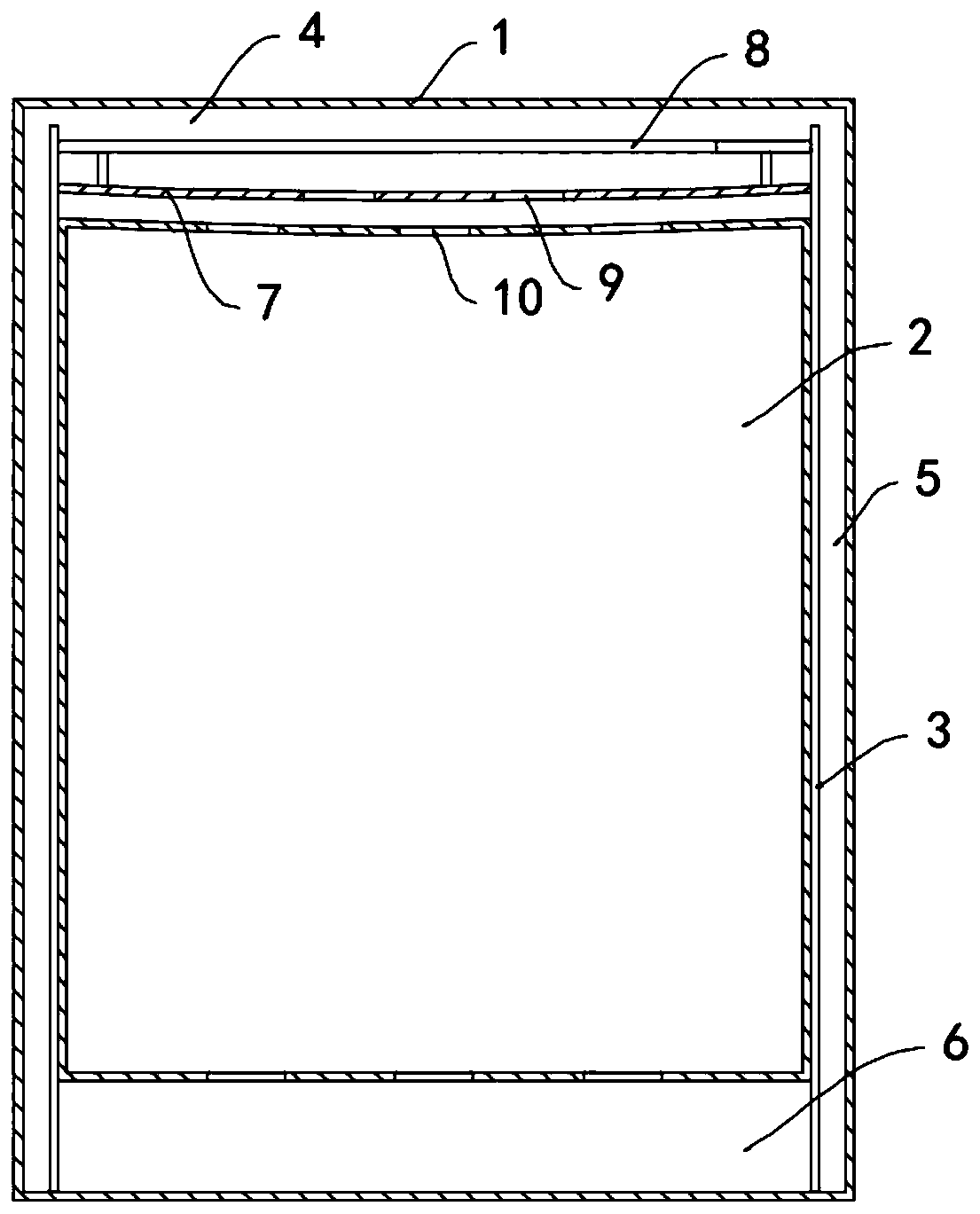
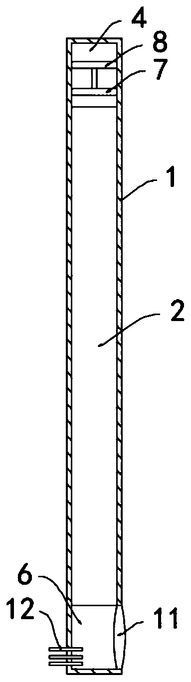
[0019] Such as Figure 1-2 As shown, a self-greasing and cleaning window for kitchens includes a frame body 1 and a light-transmitting glass 2 installed on the inner side wall of the frame body 1, and two vertical partition plates are fixedly installed in the frame body 1 3. The partition plate 3 divides the interior of the frame body 1 from top to bottom into a liquid storage chamber 4, an evaporation channel 5, and an evaporation chamber 6. The evaporation channel 5 is located on both sides of the frame body 1, and the upper end of the evaporation channel 5 and the The lower end is connected with the liquid storage chamber 4 and the evaporation chamber 6 respectively, the liquid storage chamber 4 is filled with a cleaning solution, and the cleaning liquid is an ethanol solution, and the inner wall of the liquid storage chamber 4 is sealed and slidably connected with a baffle 7, and the baffle 7 The upper surface of the upper surface is fixedly connected with a floating plate...

Embodiment 2

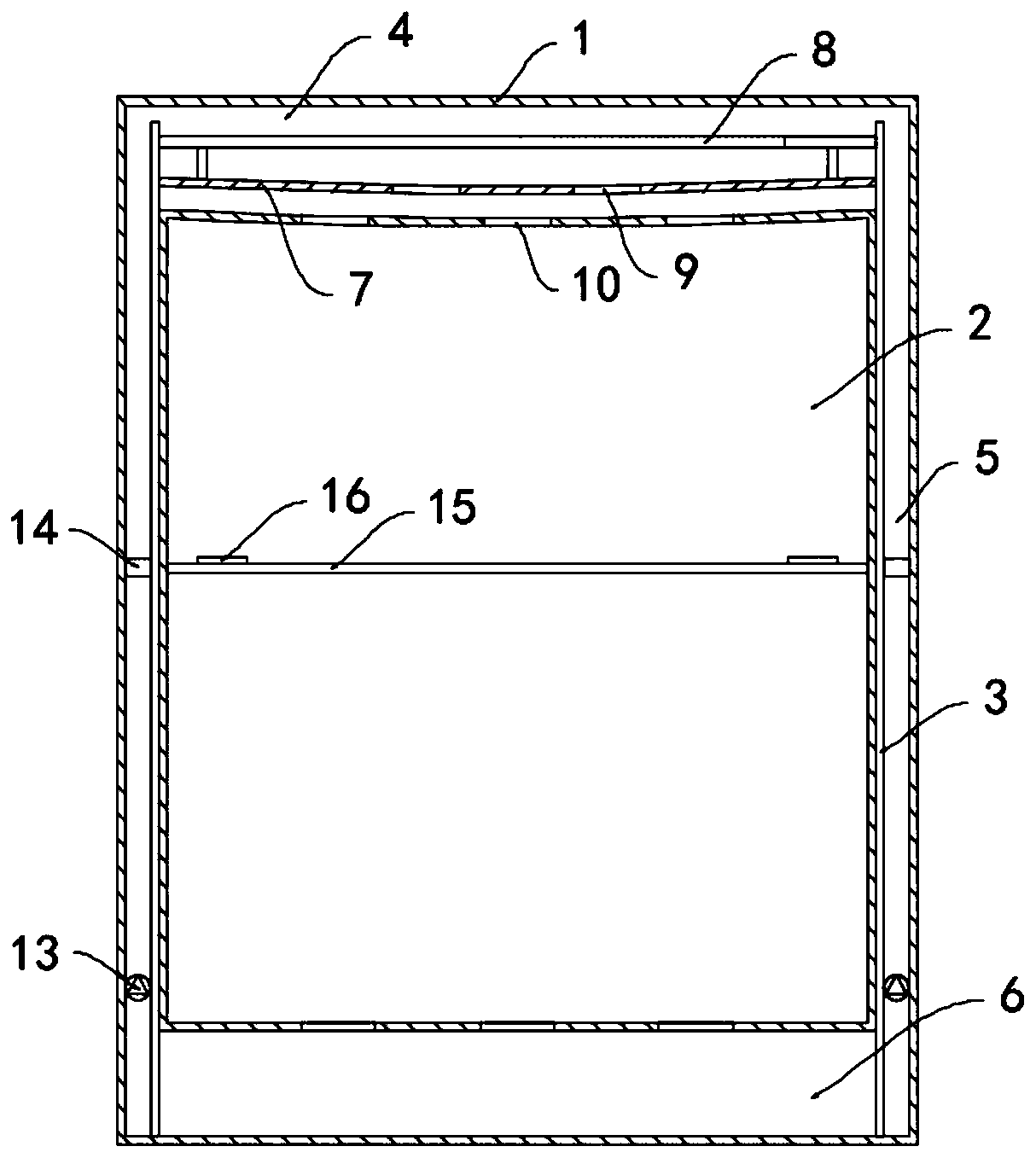
[0023] Such as image 3 As shown, the difference between this embodiment and Embodiment 1 is that a pressure valve 13 is provided in the evaporation channel 5, a permanent magnet ring 14 is slidably connected to the inner wall of the evaporation channel 5, and a permanent magnet ring 14 is slidably connected to the surface of the transparent glass 2. The scraping strip 15 is attached with a magnetic strip 16 on the side wall of the scraping strip 15, and the magnetic strip 16 and the permanent magnetic ring 14 attract each other with different poles.

[0024] In this embodiment, when the air pressure in the evaporation chamber 6 is low, the pressure valve 13 can close the evaporation channel 5. With the evaporation of the cleaning liquid in the evaporation chamber 6, the pressure in the evaporation chamber 6 gradually increases until the pressure reaches a certain value. At this time, the pressure valve 13 is opened, and the gaseous cleaning liquid enters the liquid storage ch...


PUM


Abstract

The invention belongs to the field of smart homes, and particularly relates to a self-oil-removing cleaning window for a kitchen. A frame and light transmitting glass arranged on the side wall of theinner circle of the frame are included. Two vertically-arranged separation plates are fixedly arranged in the frame and divide the interior of the frame into a liquid storage cavity, an evaporation channel and an evaporation cavity from top to bottom. The evaporation channel is located on the two sides of the frame, and the upper end and the lower end of the evaporation channel communicate with the liquid storage cavity and the evaporation cavity correspondingly. The liquid storage cavity is filled with cleaning liquid. The inner side wall of the liquid storage cavity is in sealed sliding connection with a flow stop plate. The upper surface of the flow stop plate is fixedly connected with a floating plate through a connecting rod, and the floating plate floats above the liquid surface of the cleaning liquid. In the self-oil-removing cleaning window, the cleaning liquid can dissolve oil dirt on the surface of the transparent glass and flows into the evaporation cavity, the function of removing the oil dirt on the surface of the transparent glass is achieved, the cleaning liquid in the evaporation cavity is evaporated and separated from the oil dirt, gas-state cleaning liquid entersthe liquid storage cavity to be cooled again, and cyclic utilization is achieved.

Description

technical field [0001] The invention belongs to the field of smart home, and in particular relates to a kitchen self-greasing and cleaning window. Background technique [0002] Windows are an essential part of a house to ensure indoor ventilation and lighting. Modern windows are composed of three parts: window frames, glass and movable components (hinges, handles, pulleys, etc.). As well as the improvement of human living standards, the structure of windows is becoming more and more complex to meet higher thermal requirements. [0003] Most of the traditional kitchens are equipped with windows for ventilation and lighting. However, because the kitchen will generate a lot of oil fume, it is easy to adhere to the glass. Over time, more oil stains tend to accumulate on the windows, which not only affects the appearance, but also greatly reduces Because of its lighting effect, it is necessary to brush the windows frequently, and the removal of oil stains is very difficult, and ...

Claims


Application Information

Patent Timeline
IPC IPC(8): F24S23/30E06B3/06E06B7/28B08B3/08
CPCB08B3/08E06B3/06E06B7/28F24S23/30Y02E10/40
Inventor 袁叶霞
Owner 袁叶霞
Why Eureka
Try Eureka