A dynamic electrical stress applying device and testing method for a power semiconductor device

A power semiconductor and application device technology, which is applied to the device for applying dynamic electrical stress of power semiconductor devices, the reliability test of power semiconductor devices, and the testing field of dynamic electrical stress of power semiconductor devices, can solve the failure of high-voltage power semiconductor devices and shorten the device. life, degradation of electrical characteristics, etc., to achieve the effect of protecting damage and improving efficiency

Active Publication Date: 2022-06-21
SOUTHEAST UNIV +1
View PDF19 Cites 0 Cited by
  • Summary
  • Abstract
  • Description
  • Claims
  • Application Information

AI Technical Summary

Problems solved by technology

Among them, the hot carrier injection (Hot Carrier Injection, HCI) effect of power semiconductor devices is a very important reliability item of power semiconductor devices. The electrical characteristics such as on-resistance and saturation current degrade, shortening the life of the device
[0003] Since traditional HCI reliability tests are mainly aimed at low-voltage metal-oxide-semiconductor field-effect transistors (MOSFETs), the corresponding test equipment can only provide static electrical stress
With the development of high-voltage power semiconductor technology, more and more high-voltage power semiconductor devices are designed and manufactured. Since high-voltage power semiconductor devices often work in a state of continuous switching, if only the method of increasing the stress voltage of high-voltage power semiconductor devices , high-voltage power semiconductor devices will fail too quickly due to heat accumulation, and normal reliability testing cannot be performed

Method used


Image

  • A dynamic electrical stress applying device and testing method for a power semiconductor device
  • A dynamic electrical stress applying device and testing method for a power semiconductor device
  • A dynamic electrical stress applying device and testing method for a power semiconductor device

Examples


Embodiment Construction

[0032] In order to facilitate understanding of the present invention, the present invention will be described more fully hereinafter with reference to the related drawings. Preferred embodiments of the invention are shown in the accompanying drawings. However, the present invention may be embodied in many different forms and is not limited to the embodiments described herein. Rather, these embodiments are provided so that this disclosure will be thorough and complete.

[0033]Unless otherwise defined, all technical and scientific terms used herein have the same meaning as commonly understood by one of ordinary skill in the art to which this invention belongs. The terms used herein in the description of the present invention are for the purpose of describing specific embodiments only, and are not intended to limit the present invention. As used herein, the term "and / or" includes any and all combinations of one or more of the associated listed items.

[0034] It will be under...


PUM


Abstract

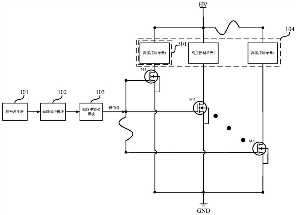
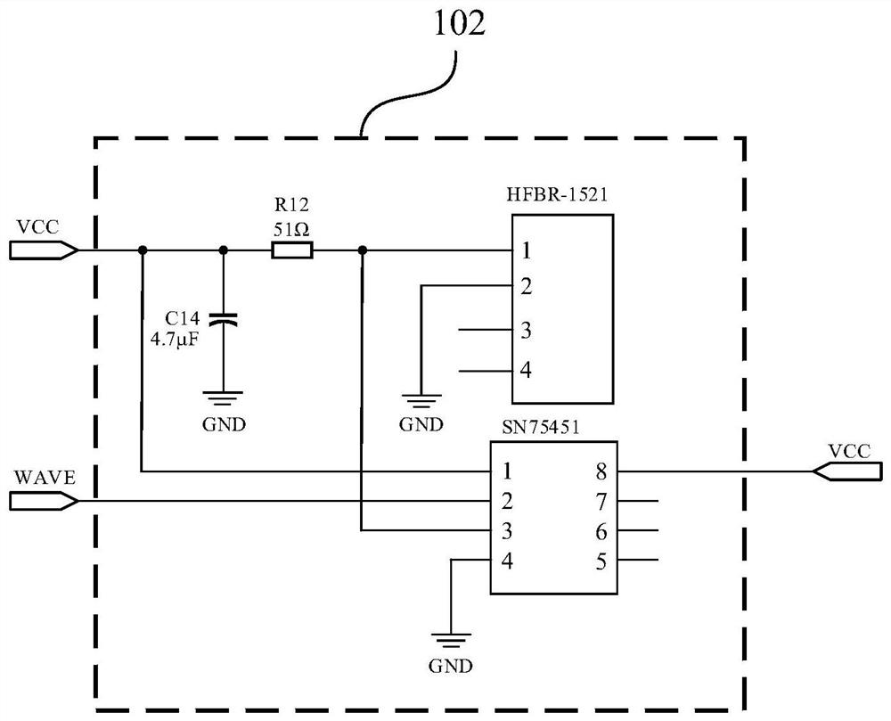
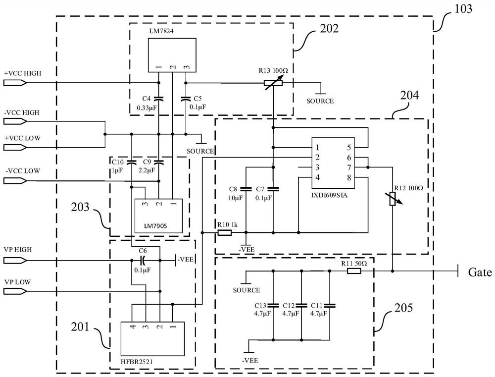
The invention relates to a dynamic electrical stress application device for power semiconductor devices, comprising: a signal generator, an optocoupler protection module, a gate pulse drive module, a high-voltage control module and the n measured power semiconductor devices, wherein the signal generation The device, the optocoupler protection module, and the gate pulse drive module are sequentially connected to the gates of the n power semiconductor devices under test, and the high voltage control module is connected to the drains of the n power semiconductor devices under test. The source stages of the n tested power semiconductor devices are grounded. The invention also relates to a dynamic electrical stress test method for a power semiconductor device. The invention can simultaneously complete the application of dynamic electrical stress to one or more power semiconductor devices under test, realizes the photoelectric isolation between the signal generator and the high-voltage circuit through the optocoupler protection module, and facilitates the monitoring of the degradation parameters of the power semiconductor devices under test , improving the efficiency of hot-carrier reliability testing under dynamic electrical stress conditions.

Description

technical field [0001] The invention relates to reliability testing of power semiconductor devices, in particular to a device for applying dynamic electrical stress to power semiconductor devices, and to a method for testing dynamic electrical stress of power semiconductor devices, belonging to the technical field of integrated circuits. Background technique [0002] In semiconductor manufacturing, power semiconductor devices are generally not put into use immediately after they are produced, but the reliability and actual service life of the power semiconductor devices should be tested by using relevant reliability tests. Among them, the hot carrier injection (HCI) effect of power semiconductor devices is a very important reliability item of power semiconductor devices, which reflects the power semiconductor devices under high voltage conditions due to hot carrier injection. The electrical characteristics such as on-resistance and saturation current are degraded, shortening...

Claims


Application Information

Patent Timeline
Patent Type & Authority Patents(China)
IPC IPC(8): G01R31/26
CPCG01R31/2601
Inventor 刘斯扬李智超叶然卢丽孙伟锋苏巍马书嫏华晓春顾力晖林峰
Owner SOUTHEAST UNIV
Why Eureka
Try Eureka