Current transformer assembly

A technology for current transformers and components, applied in the transformer/inductor shell, transformer/reactor installation/support/suspension and other directions, can solve the problems of easy shaking, lack of support and positioning structure, unfavorable assembly, etc., to achieve convenient installation Simple installation and assembly process, and the effect of preventing axial shaking

Pending Publication Date: 2020-07-17
DELIXI ELECTRIC
View PDF1 Cites 0 Cited by
  • Summary
  • Abstract
  • Description
  • Claims
  • Application Information

AI Technical Summary

Problems solved by technology

[0003] In the above-mentioned patents, the zero-sequence transformer mainly relies on a number of flexible wires to achieve its tensioned positioning, lacks a stable supporting positioning structure, and is prone to shaking, which is not conducive to assembly, and even the wires may be entangled or interfere with each other. , resulting in poor contact of the product and affecting the service life

Method used


Image

  • Current transformer assembly
  • Current transformer assembly
  • Current transformer assembly

Examples


Embodiment Construction

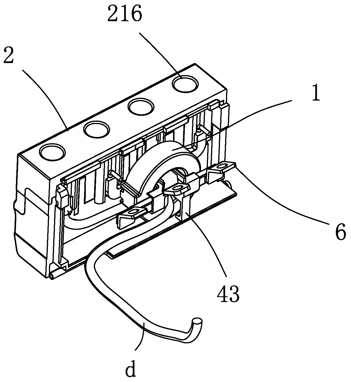
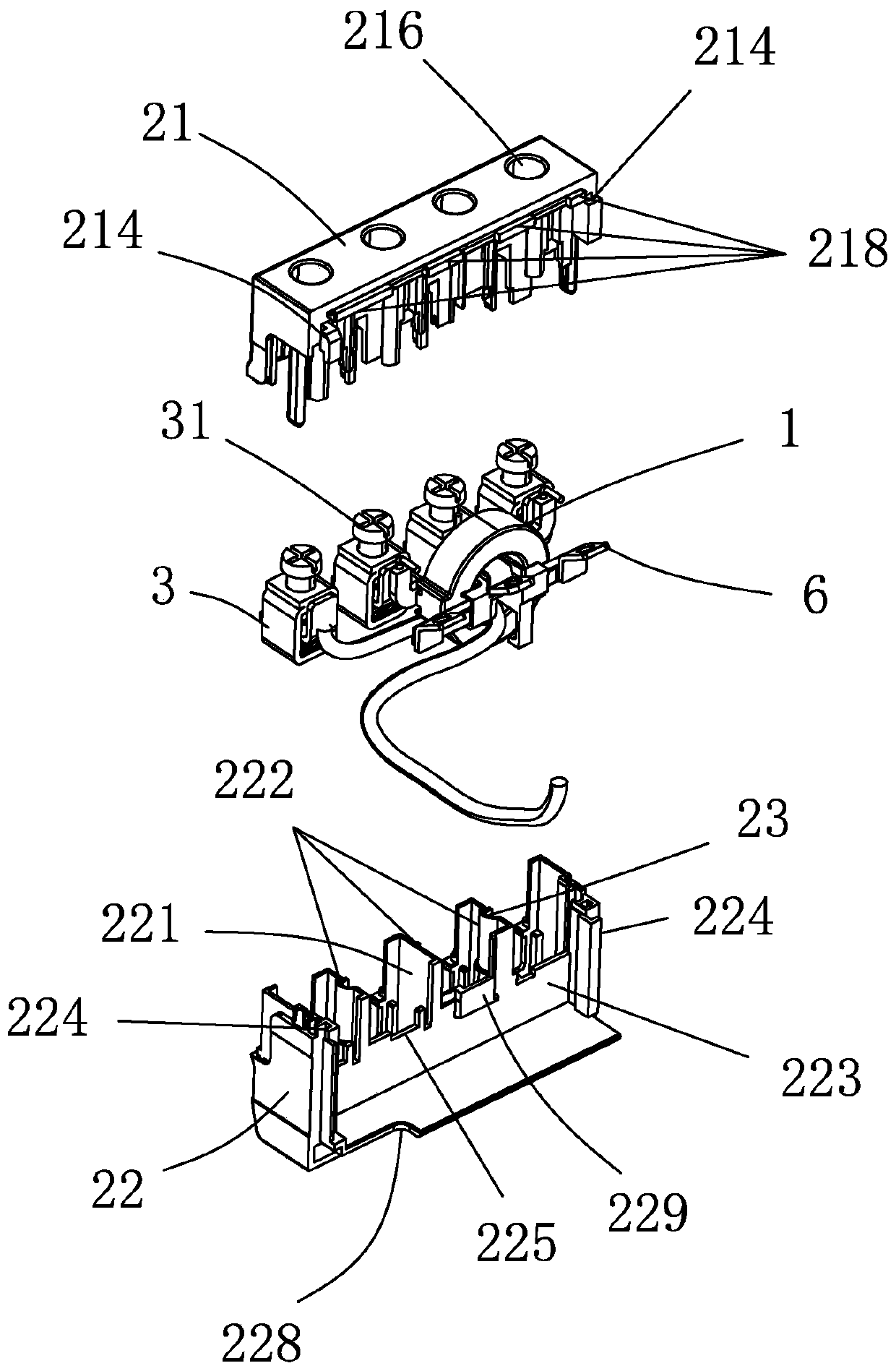
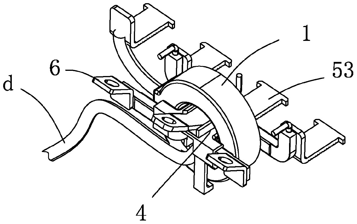
[0045] A current transformer assembly of the present invention is used to form a component of a multi-level circuit breaker, and its embodiment is as follows Figure 1-15 Shown: includes a ring-shaped current transformer 1, a housing 2 for accommodating the current transformer 1, a number of current-carrying parts, and a terminal block 3 correspondingly connected to these current-carrying parts, and is installed in cooperation with the current transformer 1 The fixed part also includes a support 4, the current-carrying parts are made of rigid conductive material, have good conductivity and are not easy to bend, the support 4 is made of insulating material, and these current-carrying parts are connected with the support 4 at the same time Fitted together and fixed in the inner hole of the current transformer 1, the support member 4 can support and position the current-carrying parts penetrating into the current transformer 1, and at the same time enhance the insulation function ...


PUM


Abstract

The invention discloses a current transformer assembly which comprises an annular current transformer, a shell used for containing the current transformer, a plurality of current-carrying components and wire holders correspondingly connected with the current-carrying components respectively. Supporting components are also installed and fixed in a way of being cooperated with the current transformer. The current-carrying components are made of rigid conductive materials, and the current-carrying components are matched with the supporting components to be fixedly arranged in the inner hole of the current transformer in a penetrating manner. The assembly process is simple and operation is more stable.

Description

technical field [0001] The invention relates to a current transformer assembly. Background technique [0002] CN207664003U discloses a leakage circuit device, which includes a multi-level circuit breaker main body, a leakage module main body, an upper cover, a base, and a partition housing arranged between the upper cover and the base, arranged on both sides of the multi-level circuit breaker main body and The wiring terminals on both sides of the main body of the leakage module, the main body of the multi-level circuit breaker and the main body of the leakage module are arranged side by side, and the main body of the multi-level circuit breaker includes a moving contact, a static contact, a tripping mechanism, a moving iron core, a static iron Core, the coil surrounding the static iron core, one end of the coil is connected to the static contact, and the other end is provided with a conversion connecting piece (that is, a circuit breaker connecting plate), and a connection ...

Claims


Application Information

Patent Timeline
IPC IPC(8): H01F27/02H01F27/06
CPCH01F27/02H01F27/06
Inventor 徐方剑王刚祁卫华
Owner DELIXI ELECTRIC
Why Eureka
Try Eureka