
Temperature control system of energy storage container and energy storage container

A temperature control system and container technology, applied in electrical components, electrochemical generators, batteries, etc., can solve problems such as poor temperature consistency of battery boxes, uneven distribution of cold air flow, and large energy storage containers

Pending Publication Date: 2020-07-17
HUBEI JINQUAN NEW MATERIALS CO LTD
View PDF9 Cites 6 Cited by
  • Summary
  • Abstract
  • Description
  • Claims
  • Application Information

AI Technical Summary

Problems solved by technology

[0003] Due to the large size of the energy storage container and the large battery capacity, the cold air flow in the energy storage container is unevenly distributed, so that there is a large temperature difference between the battery boxes in the energy storage container during the charging and discharging process, and the temperature of the battery boxes is consistent. Poor, it is easy to cause the temperature of the batteries in some battery boxes to be too high and affect their life

Method used


Image

  • Temperature control system of energy storage container and energy storage container
  • Temperature control system of energy storage container and energy storage container
  • Temperature control system of energy storage container and energy storage container

Examples


Embodiment Construction

[0032] In order to make the technical problems solved by the present invention, the technical solutions adopted and the technical effects achieved clearer, the technical solutions of the embodiments of the present invention will be further described in detail below in conjunction with the accompanying drawings. Obviously, the described embodiments are only the technical solutions of the present invention. Some, but not all, embodiments. Based on the embodiments of the present invention, all other embodiments obtained by those skilled in the art without making creative efforts belong to the protection scope of the present invention.

[0033] In the description of the present invention, unless otherwise clearly specified and limited, the terms "connected", "connected" and "fixed" should be understood in a broad sense, for example, it can be a fixed connection, a detachable connection, or an integrated ; It can be a mechanical connection or an electrical connection; it can be a d...


PUM


Abstract

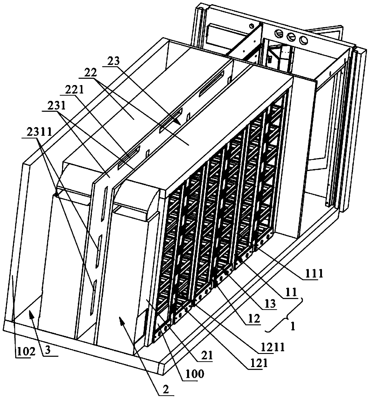
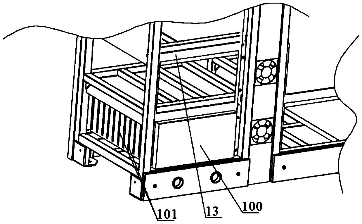
The invention belongs to the technical field of energy storage equipment. The temperature control system of the energy storage container is used for cooling a battery box in the energy storage container, and comprises at least two battery rack groups which are arranged side by side, each battery rack group comprises a plurality of battery racks which are arranged side by side, and each battery rack group is provided with a plurality of accommodating spaces for accommodating the battery box; one of a static pressure bin and an air exhaust bin is arranged between every two adjacent battery racksin each battery rack group, the static pressure bins and the air exhaust bins are alternately distributed, and air exhaust holes are formed in the air exhaust bins; the two opposite sides of the containing space are correspondingly communicated with the static pressure bin and the exhaust bin respectively. The cold air assembly comprises a refrigerating device and an air supply pipe, an air storage bin is arranged between every two adjacent battery rack sets, the air storage bins are communicated with the static pressure bins respectively, and an air outlet of the refrigerating device is communicated with the air storage bins through the air supply pipe. Cold air in the temperature control system is uniformly distributed, so that the temperature of each battery box can be kept consistent.

Description

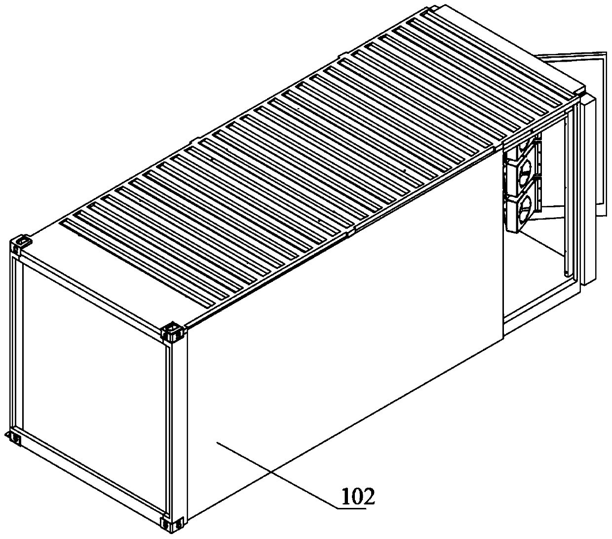
technical field [0001] The invention relates to the technical field of energy storage equipment, in particular to a temperature control system of an energy storage container and the energy storage container. Background technique [0002] As a kind of electric energy storage and transfer equipment, the energy storage container has the characteristics of large capacity, short construction period, high reliability, flexible installation and scheduling, and strong environmental adaptability. It can be configured at the power generation end, transmission and distribution end, and user end. Widely used in power industry. Energy storage containers are mainly composed of battery boxes, converters, transformers, monitoring cabinets, fire protection systems, temperature control systems, etc. As an energy storage component, the battery box plays a key role in the overall performance of the energy storage container. [0003] Due to the large size of the energy storage container and th...

Claims


Application Information

Patent Timeline
Patent Type & Authority Applications(China)
IPC IPC(8): H01M2/10H01M10/613H01M10/617H01M10/627H01M10/6556H01M10/6563
CPCH01M10/613H01M10/617H01M10/627H01M10/6556H01M10/6563H01M2220/10H01M50/20Y02E60/10
Inventor 蔡鹏魏泽席蒙玉宝陈翔
Owner HUBEI JINQUAN NEW MATERIALS CO LTD
Learn More