Power battery cooling and heating system

A power battery and heating system technology, which is applied to secondary batteries, circuits, electrical components, etc., can solve the problems of cooling water flow obstruction, poor stability and reliability, and low efficiency, so as to improve reliability and stability, and ensure fast Flow, the effect of improving heat exchange efficiency

Active Publication Date: 2020-07-17
DONGFENG MOTOR CORP HUBEI
View PDF14 Cites 2 Cited by
  • Summary
  • Abstract
  • Description
  • Claims
  • Application Information

AI Technical Summary

Problems solved by technology

However, due to the fact that the air heating medium is prone to noise during the flow and heat exchange process, and the heat exchange efficiency is low, it is gradually replaced by heating and cooling with liquid as the medium. The current cooling and heating structure with liquid as the medium has high heat exchange efficiency and low noise , good temperature field uniformity, etc.; but at the same time, there are also high costs, heating needs to be realized by heating the liquid multiple times outside, low efficiency, many rubber hose joints, and the risk of aging and leakage, etc.
[0003] The Chinese utility model whose publication number is CN 208939114U discloses a water-cooled plate for an electric vehicle power battery and a battery pack containing the water-cooled plate. The plate is fixed, and the defects of this patent are: 1. There is no heating function on the harmonica tube, and the liquid needs to be heated by the outside for multiple times to heat up the battery in a low temperature environment, which is inefficient; 2. The water inlet and outlet pipes of the water cooling plate are rubber hoses, which are aging Leakage risk. When the battery module is fixed on the water-cooled plate and the water-cooled plate is pressed down, since the front end of the water inlet and outlet pipes is fixed on the battery pack shell, the front of the water inlet and outlet pipes will warp upwards to form stress, resulting in poor stability here. The reliability is poor, and the squeezed water pipe will also hinder the flow of cooling water

Method used


Image

  • Power battery cooling and heating system
  • Power battery cooling and heating system
  • Power battery cooling and heating system

Examples


Embodiment Construction

[0034] The present invention will be further described in detail below in conjunction with the accompanying drawings and specific embodiments.

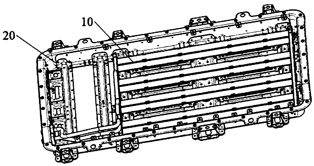
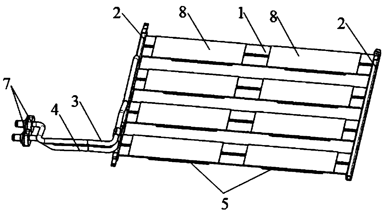
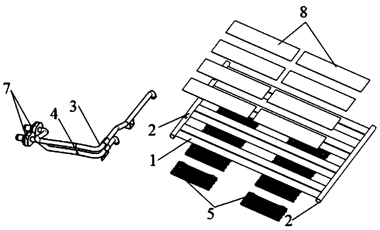
[0035] Such as Figure 1-11 As shown, the electric vehicle power battery cooling and heating system provided by the present invention includes a battery pack housing 20 and a water cooling plate 10 disposed in the battery pack housing 20, and the water cooling plate 10 includes harmonicas that communicate together to form a liquid medium flow channel Tube 1, collecting pipe 2, water inlet pipe 3, and water outlet pipe 4. The collecting pipe 2 is located on both sides of the harmonica pipe 1, and also includes a heating device arranged under the water cooling plate 10. The heating device includes a bottom surface of the harmonica pipe 1. The electric heating sheet 5 and the supporting elastic piece 6 below the electric heating sheet 5 are located on the bottom surface of the battery pack housing 20 to vertically elastically support the...


PUM


Abstract

The invention provides an electric vehicle power battery cooling and heating system which comprises a battery pack shell and a water cooling plate arranged in the battery pack shell. The water coolingplate comprises a harmonica-shaped pipe, a flow collecting pipe, a water inlet pipe and a water outlet pipe. The system is characterized by further comprising a heating device body arranged below thewater cooling plate, the heating device comprises an electric heating piece attached to the bottom face of the harmonica-shaped pipe and a supporting elastic piece below the electric heating piece, and the supporting elastic piece is located on the bottom face of the battery pack shell to vertically and elastically support the electric heating piece. The water inlet pipe and the water outlet pipeare respectively provided with a pipe orifice assembly which has a moving space with the battery pack shell in the axial direction and the radial direction. After the battery module is installed, thesupporting elastic piece is in a compressed state, and certain supporting force can be provided so that contact of the heat exchange faces between the electric heating piece and the harmonica-shapedpipe is effectively guaranteed, the heat exchange efficiency is improved, and size out-of-tolerance caused by buckling deformation of the harmonica-shaped pipe can be absorbed.

Description

technical field [0001] The invention relates to a power battery of an electric vehicle, in particular to a cooling and heating system for the power battery of an electric vehicle. Background technique [0002] At present, the energy storage equipment of electric vehicles is mainly based on lithium-ion power battery packs, but the environmental adaptability and insufficient service life of lithium-ion battery packs limit its further promotion and application. In order to solve the above defects, in the prior art, a battery pack heating or cooling system using liquid or air as the medium is installed in the lithium-ion battery pack to make the power battery work in the optimal operating temperature range, which can improve its environmental adaptability, use characteristics such as lifespan. However, due to the fact that the air heating medium is prone to noise during the flow and heat exchange process, and the heat exchange efficiency is low, it is gradually replaced by heat...

Claims


Application Information

Patent Timeline
Patent Type & Authority Applications(China)
IPC IPC(8): H01M10/613H01M10/615H01M10/625H01M10/6554H01M10/6556H01M10/6567H01M10/6571
CPCH01M10/613H01M10/615H01M10/625H01M10/6554H01M10/6556H01M10/6567H01M10/6571Y02E60/10
Inventor 刘爽夏洋王玉姣怀慧潘丽娜
Owner DONGFENG MOTOR CORP HUBEI
Why Eureka
Try Eureka